
Nissan Armada 2025-2026 Service and Repair Manual: Removal and Installation
WARNING:
CAUTION:
Front bumper fascia assembly is made of resin. Never apply excessive force to it, and be careful to prevent contact with oil.
REMOVAL
Remove front grille. Refer to Removal and Installation.
Remove fillet molding (with fillet molding). Refer to Removal and Installation.
Remove front bumper energy absorber A.
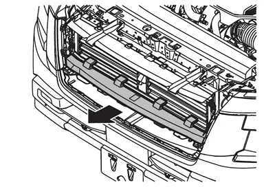
Disengage active grille shutter fixing clips  .
.
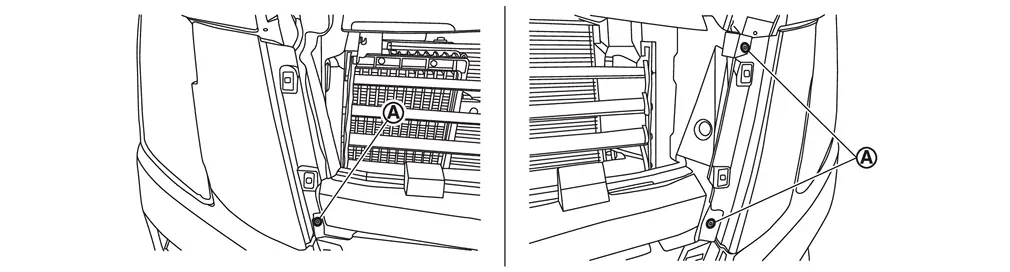
Disengage fixing clips and pawls, and then remove front bumper side finisher (LH and RH).
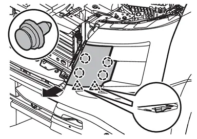
 | : Clip |
 | : Pawl |
Remove front bumper fascia fixing clips .
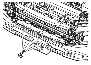
Remove fixing bolts .
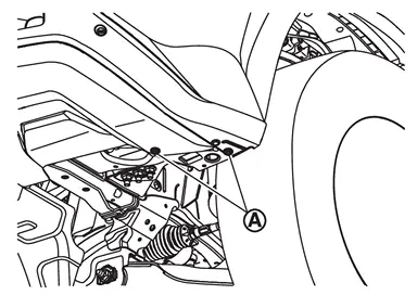
Remove fixing bolts .
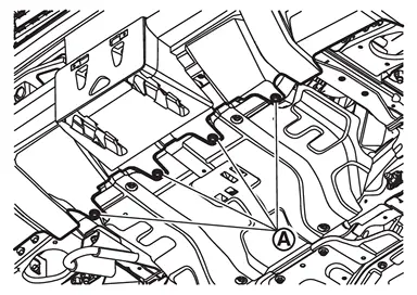
Remove fixing screws .
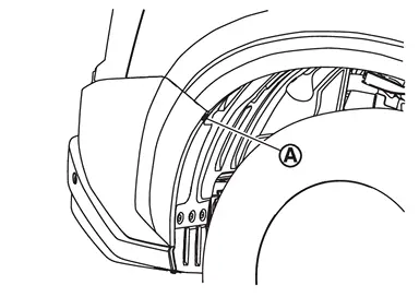
Apply protective tapes (A) on the part to protect it from damage.
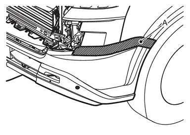
Pull front bumper fascia assembly side toward the vehicle side to disengage the fitting of front bumper side bracket and front bumper fascia assembly side according to the numerical order 1→2 as shown by the arrows in the figure.
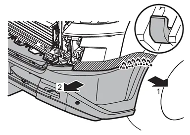
| : Pawl |
CAUTION:
When disengage front bumper fascia assembly, 2 workers are required so as to prevent it from dropping.
Disconnect front sonar sensor harness connector.
Remove front bumper fascia assembly.
CAUTION:
When removing front bumper fascia assembly, 2 workers are required so as to prevent it from dropping.
Remove the following parts after removing front bumper fascia assembly.
Front sonar sensor. Refer to SONAR SENSOR (FRONT) : Removal & Installation.
License plate bracket
Front bumper protector (if equipped)
U nuts
Front bumper finisher
Grommets (if equipped)
Remove mounting nuts, and then remove front bumper retainer upper.
Remove mounting bolts, and then remove front bumper side retainer (LH and RH).
Remove active grille shutter fixing clip and mounting nuts. Refer to Exploded View.
Remove mounting nuts, and then remove front bumper reinforcement.
Remove mounting bolts, and then remove front bumper side stay (LH and RH).
Remove front bumper energy absorber B (LH and RH).
Remove front bumper energy absorber C (LH and RH).
Disengage fixing pawls, and then remove front bumper energy absorber D.
Remove front bumper side bracket (LH and RH) fixing screws.
Disengage fixing pawls, and then remove front bumper side bracket (LH and RH).
INSTALLATION
Note the following items, and then install in the reverse order of removal.
CAUTION:
Always replace front bumper energy absorber A with a new one.
Always replace double-sided tapes with new ones, if front bumper protector is reused (if equipped).
If the retainer is removed from the front bumper protector, replace the double-sided tapes with new ones (if equipped).
Remove double-sided tapes remaining on front bumper fascia and back of front bumper protector with double-sided tape remover, after removing front bumper protector (if equipped).
Degrease front bumper fascia mounting surface of front bumper protector, before apply primer (if equipped).
Press-fit the entire area of the double-sided tape with 49 N (5 kg) or more of pressure after applying license plate bracket and front bumper protector on the front bumper protector (if equipped).
Apply the double-sided tapes to the license plate bracket and front bumper protector so that it do not protrude beyond the marking line (if equipped).
Never wash the vehicle within 24 hours after installing so as to keep adhesive.
 NOTE:
NOTE:
Fitting adjustment cannot be performed.
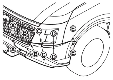
Portion Clearance Surface height difference Front bumper fascia assembly – Front grille – 0.5 - 3.5 mm
(0.020 - 0.138 in)—  –
– 0.5 - 3.5 mm
(0.020 - 0.138 in)— Front bumper fascia assembly – Front bumper side finisher  –
– 0.1 - 1.9 mm
(0.004 - 0.075 in)0.1 - 1.9 mm
(0.004 - 0.075 in)Front bumper fascia assembly – Front combination lamp  –
– 1.6 - 4.2 mm
(0.063 - 0.165 in)— Front bumper fascia assembly – Front fender assembly  –
– 0.1 - 0.9 mm
(0.004 - 0.035 in)(–0.5) – (+1.5) mm
[(–0.020) – (+0.059) in]If front bumper fascia is replaced with new one, make holes for license plate bracket installation in front bumper fascia with a drill as shown in the figure.
Without front bumper protector models
Hold the license plate bracket
 to the front bumper fascia and mark two locations .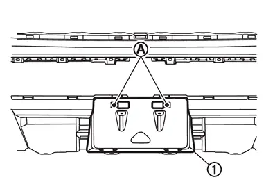
Remove the license plate bracket and drill two square holes in the locations marks
in the previous step.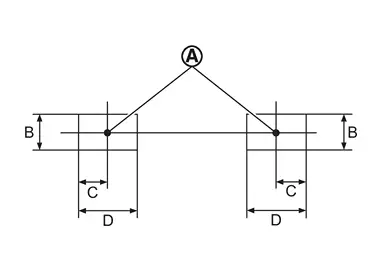
B : 26.0 mm (1.02 in) C : 19.0 mm (0.75 in) D : 71.5 mm (2.81 in) Install u nuts.
Install grommets.
Make holes for license plate bracket installation in front bumper fascia with a drill as shown in the figure.
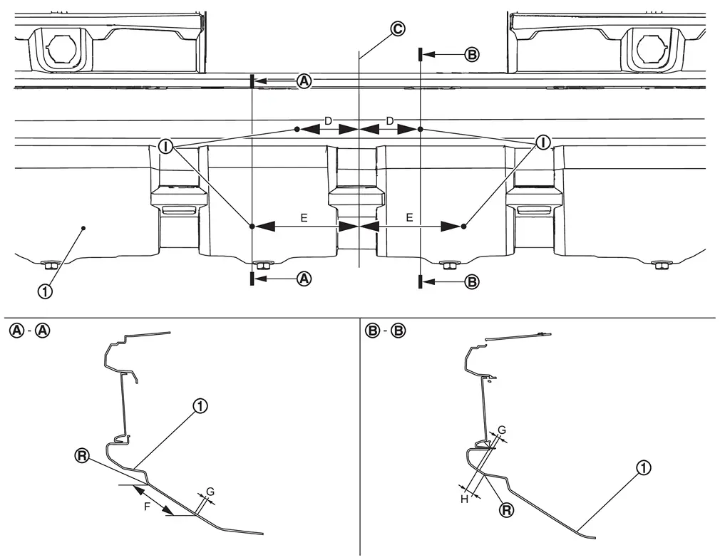
Front bumper fascia Vehicle center 
License plate bracket installation hole 
R end Dimension D: Distance from vehicle center : 64.0 mm (2.520 in) E: Distance from vehicle center : 130.0 mm (5.118 in) F: Distance from R end of front bumper fascia : 59.3 mm (2.335 in) G: Hole size : φ 9.0 mm (0.354 in) H: Distance from R end of front bumper fascia : 15.7 mm (0.618 in) Install license plate bracket with screws at the license plate bracket installation holes.
With front bumper protector models
Hold the license plate bracket
to the front bumper fascia and mark two locations .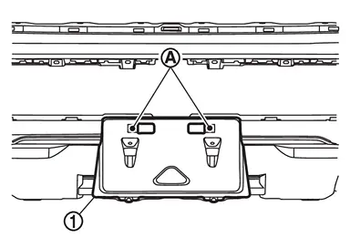
Remove the license plate bracket and drill two square holes in the locations marks
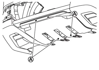
in the previous step.B : 26.0 mm (1.02 in) C : 19.0 mm (0.75 in) D : 71.5 mm (2.81 in) Install license plate bracket with screws at the license plate bracket installation hole position marks
.
 Exploded View
Front bumper side bracket RH Front bumper side retainer RH Front bumper retainer upper Front bumper side stay RH Front bumper reinforcement Front bumper energy absorber A Front bumper energy abs ...
 City Models
...
Other materials:
Exploded View
Back door weather-strip Back door hinge Back door stay* Back door stay upper bracket* Back door bumper rubber upper Back door stay lower bracket Back door bumper rubber lower Drain plug TORX bolt Back door striker Back door panel : Center mark : Seam : Matching mark : Pawl : Always re ...
Disassembly and Assembly
WARNING:
When working, be careful to prevent accidental explosion front side air bag module and front center air bag module (with front center air bag module). Refer to Precaution for Supplemental Restraint System (SRS) "AIR BAG" and "SEAT BELT PRE-TENSIONER".
CAUTION:
When disassemble, always use a ...
Removal and Installation
WARNING:
REMOVAL
Put matching mark on rear propeller shaft flange yoke and final drive companion flange.
CAUTION:
Put matching mark on rear propeller shaft flange yoke and transfer companion flange.
CAUTION:
For matching mark, use paint. Never damage propeller shaft flange and transfer compani ...

0.005