
Nissan Armada 2025-2026 Service and Repair Manual: Removal and Installation
WARNING:
CAUTION:
Front bumper fascia assembly is made of resin. Never apply excessive force to it, and be careful to prevent contact with oil.
REMOVAL
Remove front grille. Refer to Removal and Installation.
Remove front bumper energy absorber A.
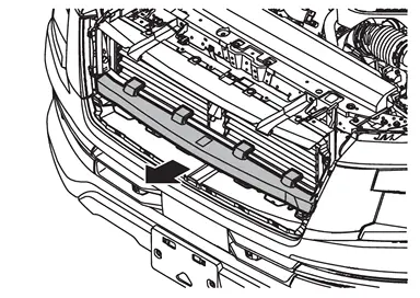
Disengage active grille shutter fixing clips  .
.
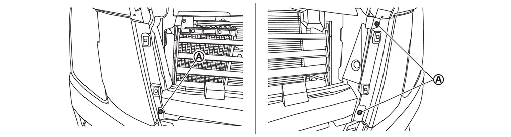
Disengage fixing clips and pawls, and then remove front bumper side finisher (LH and RH).
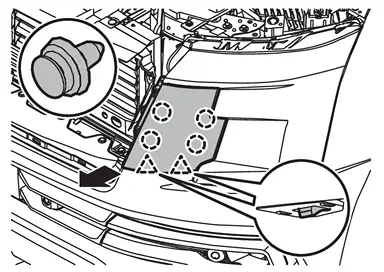
 | : Clip |
 | : Pawl |
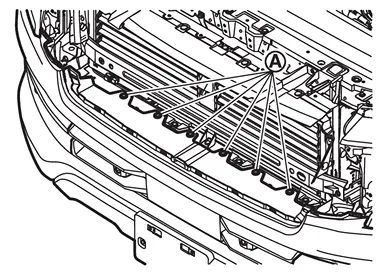
Remove front bumper fascia fixing clips .
Remove front spoiler. Refer to Removal and Installation.
Remove fixing bolts .
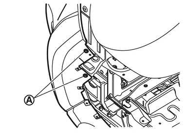
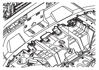
Remove fixing bolts .
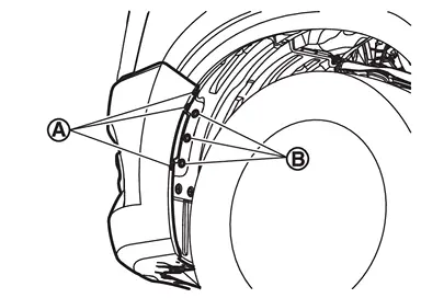
Remove fixing screws and fender protector fixing clips  .
.
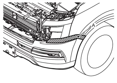
Apply protective tapes (A) on the part to protect it from damage.
Pull front bumper fascia assembly side toward the vehicle side to disengage the fitting of front bumper side bracket and front bumper fascia assembly side according to the numerical order 1→2 as shown by the arrows in the figure.
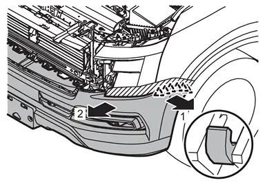
| : Pawl |
CAUTION:
When disengage front bumper fascia assembly, 2 workers are required so as to prevent it from dropping.
Disconnect front sonar sensor harness connector.
Disconnect front side radar harness connector (if equipped).
Remove front bumper fascia assembly.
CAUTION:
When removing front bumper fascia assembly, 2 workers are required so as to prevent it from dropping.
Remove the following parts after removing front bumper fascia assembly.
Front sonar sensor. Refer to SONAR SENSOR (FRONT) : Removal & Installation.
Front side radar (if equipped). Refer to Removal and Installation.
License plate bracket
U nuts
Front bumper grille
Front bumper side grille (LH and RH)
Front bumper side duct (LH and RH)
Front bumper bracket (LH and RH)
Grommets
Remove seal.
Remove mounting nuts, and then remove front bumper retainer.
Remove mounting bolts, and then remove front bumper side retainer (LH and RH).
Remove active grille shutter fixing clip and mounting nuts. Refer to Exploded View.
Remove mounting nuts, and then remove front bumper reinforcement.
Remove mounting bolts, and then remove front bumper side stay (LH and RH).
Disengage fixing pawls, and then remove front bumper energy absorber B.
Remove front bumper side bracket (LH and RH) fixing screws.
Disengage fixing pawls, and then remove front bumper side bracket (LH and RH).
INSTALLATION
Note the following items, and then install in the reverse order of removal.
CAUTION:
Perform side radar alignment (with side radar). Refer to Work Procedure.
Always replace front bumper energy absorber A and seal with a new one.
 NOTE:
NOTE:
Fitting adjustment cannot be performed.
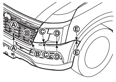
Portion Clearance Surface height difference Front bumper fascia assembly – Front grille – 0.5 - 3.5 mm
(0.020 - 0.138 in)— – 0.5 - 3.5 mm
(0.020 - 0.138 in)— Front bumper fascia assembly – Front bumper side finisher  –
– 0.1 - 1.9 mm
(0.004 - 0.075 in)0.1 - 1.9 mm
(0.004 - 0.075 in)Front bumper fascia assembly – Front combination lamp  –
– 1.6 - 4.2 mm
(0.063 - 0.165 in)— Front bumper fascia assembly – Front fender assembly  –
– 0.1 - 0.9 mm
(0.004 - 0.035 in)(–0.5) – (+1.5) mm
[(–0.020) – (+0.059) in]If front bumper fascia is replaced with new one, make holes for license plate bracket installation in front bumper fascia with a drill as shown in the figure.
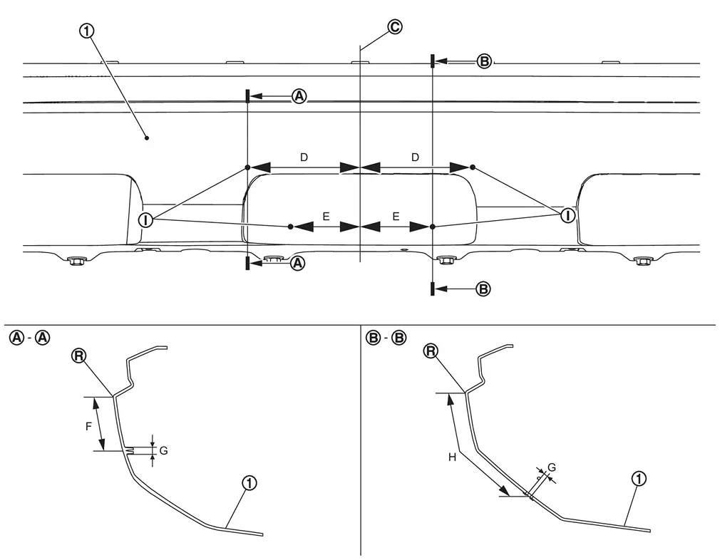

Front bumper fascia Vehicle center 
License plate bracket installation hole 
R end Dimension D: Distance from vehicle center : 127.5 mm (5.020 in) E: Distance from vehicle center : 78.6 mm (3.094 in) F: Distance from R end of front bumper fascia : 61.2 mm (2.409 in) G: Hole size : φ 5.0 mm (0.197 in) H: Distance from R end of front bumper fascia : 149.7 mm (5.894 in)
 Exploded View
Front bumper side bracket RH Front bumper side retainer RH Front bumper retainer Front bumper side stay RH Front bumper reinforcement Seal Front bumper energy absorber A Front bumper energy abs ...
 Inspection
SIDE RADAR IRRADIATION AREA
For side radar irradiation area, refer to the figure below.
Front bumper fascia Side radar irradiation area Reference point (R end) C 65 mm
(2.56 in) (character line) ...
Other materials:
Removal and Installation
WARNING:
CAUTION:
For repair and mending of irradiation area of side radar, be careful the following.
Never affix a sticker (including transparent one) or install an accessory to the detecting range of side radar.
Since it affects side radar performance, there are some restrictions on the various co ...
Diagnosis Procedure
CHECK DOOR LOCK ACTUATOR
Check door lock actuator (passenger side).
Refer to Diagnosis Procedure.
Is the inspection result normal?
YES>>
GO TO 2.
NO>>
Repair or replace the malfunctioning parts.
REPLACE BCM
Replace BCM. Refer to Removal and Installation.
Confirm the operation after rep ...
PRECAUTIONS FOR POP UP ENGINE HOOD : Precautions
WARNING:
Always observe the following items for preventing accidental activation.
Before removal or installation of the pop-up engine hood and harness, always OFF the ignition switch, disconnect the battery negative terminal, and wait for 3 minutes or more. (To discharge the accumulated electricity ...

0.0053