Rotation
WARNING:
-
Jacking up or lift up the vehicle may the vehicle height to go down which cause a personal injury and/or damage to the air suspension component parts. Refer to Precaution for when Jacking and Lifting Up the vehicle with Electronic Air Suspension System.
-
Follow the maintenance schedule for tire rotation service intervals. Refer to General Maintenance.
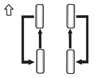
-
When installing the wheel, tighten wheel nuts to the specified torque. Refer to ROAD WHEEL TIRE : Exploded View.
CAUTION:
-
When installing wheels, tighten them diagonally by dividing the work two to three times in order to prevent the wheels from developing any distortion.
-
Be careful not to tighten wheel nut at torque exceeding the criteria.
-
Use NISSAN genuine wheel nuts for aluminum wheels.
-
-
Perform the ID registration, after tire rotation. Refer to Work Procedure.
Adjustment
WARNING:
-
Jacking up or lift up the vehicle may the vehicle height to go down which cause a personal injury and/or damage to the air suspension component parts. Refer to Precaution for when Jacking and Lifting Up the vehicle with Electronic Air Suspension System.
BALANCING WHEELS (BONDING WEIGHT TYPE)
Preparation Before Adjustment
Using releasing agent, remove double-faced adhesive tape from the road wheel.
CAUTION:
-
Be careful not to scratch the road wheel during removal.
-
After removing double-faced adhesive tape, wipe clean traces of releasing agent from the road wheel.
Wheel Balance Adjustment
-
If a tire balance machine has adhesion balance weight mode settings and drive-in weight mode setting, select and adjust a drive-in weight mode suitable for road wheels.
-
The details of the adjustment procedure are different for each model of wheel balancer. Therefore, refer to each instruction manual.
Set road wheel on tire balance machine using the center hole as a guide. Start the tire balance machine.
CAUTION:
-
Never install the inner balance weight before installing the outer balance weight.
-
Before installing the balance weight, always to clean the mating surface of the road wheel.
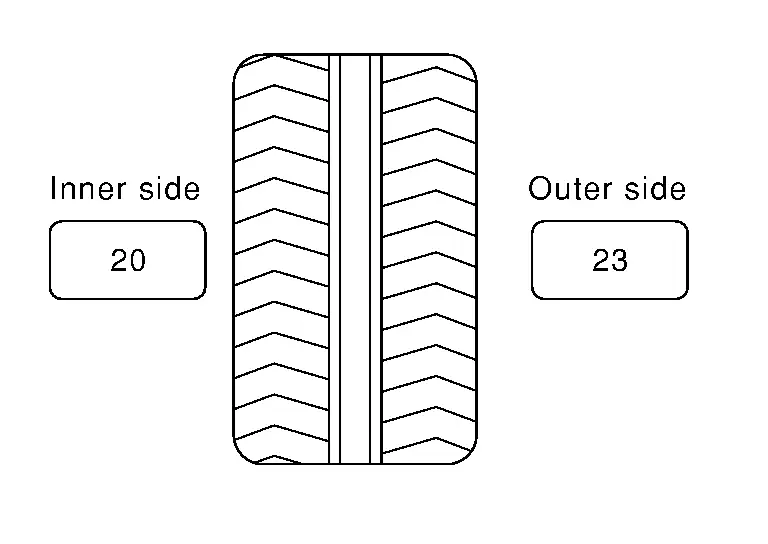
Calculation example:
23 g (0.81 oz) × 5/3 = 38.33 g (1.35 oz) ⇒ 37.5 g (1.32 oz) balance weight (closer to calculated balance weight value)
 NOTE:
NOTE:
Note that balance weight value must be closer to the calculated balance weight value.
Example:
36.2 ⇒ 35 g (1.23 oz)
36.3 ⇒ 37.5 g (1.32 oz)
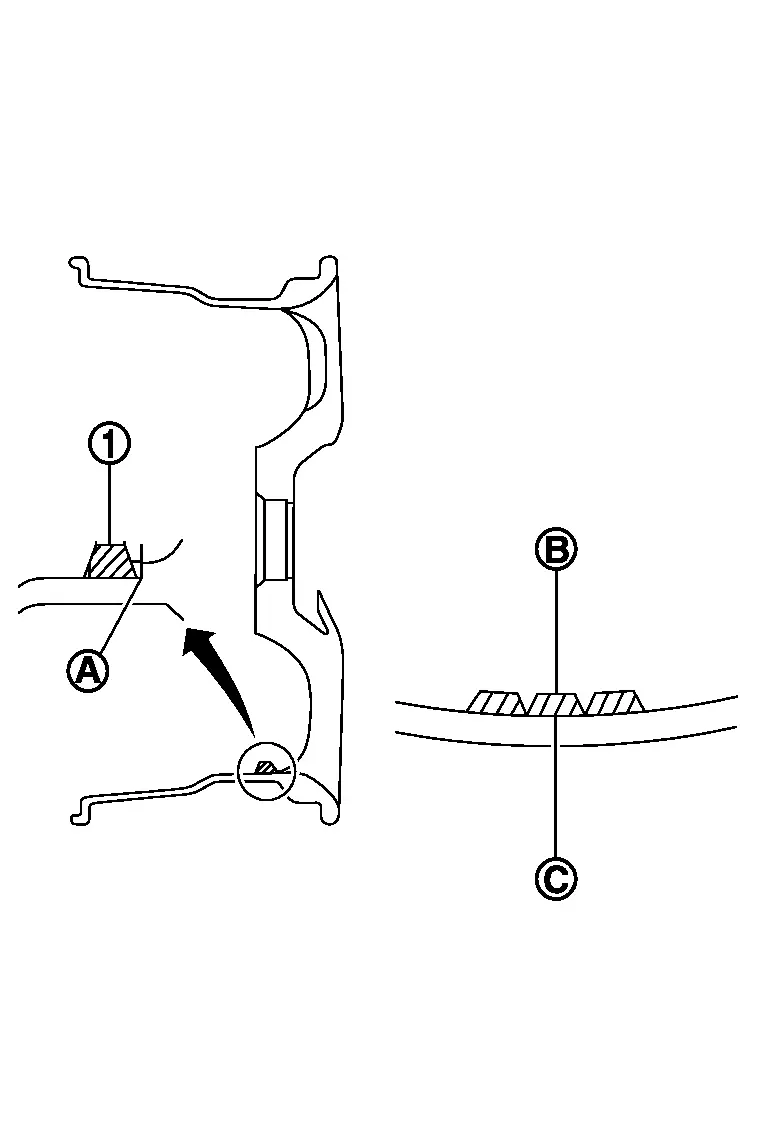
Installed balance weight in the position.-
When installing balance weight
 to road wheels, set it into the grooved area
  on the inner wall of the road wheel as shown in the figure so that the balance weight center
  is aligned with the tire balance machine indication position (angle)
  .
.
CAUTION:
-
Always use genuine NISSAN adhesion balance weights.
-
Balance weights are non-reusable; always replace with new ones.
-
Never install more than four sheets of balance weight.
-
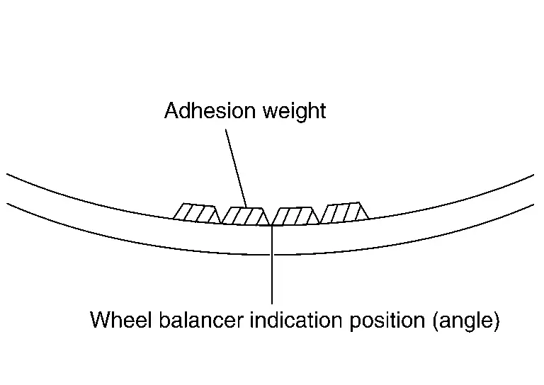
CAUTION:
Never install one balance weight sheet on top of another.
Start the tire balance machine again.
Install drive-in balance weight on inner side of road wheel in the tire balance machine indication position (angle).
CAUTION:
Never install more than two balance weight.
Start the tire balance machine. Check that the inner and outer residual unbalance value is within the allowable unbalance value.
CAUTION:
If either residual unbalance value exceeds limit, repeat installation procedures.
| Allowable unbalance value | |
| Dynamic (At flange) | : Refer to ROAD WHEEL : Service Data. |
| Static (At flange) | :Refer to ROAD WHEEL : Service Data. |
Other materials
Condenser
Exploded View
Radiator
Condenser outlet pipe
O-ring
Condenser & liquid tank assembly
Condenser seal
Refrigerant pressure sensor
Condenser inlet pipe
: Pawl
: Always replace after every disassembly.
: N·m (kg-m, in-lb)
, , : Indicate ...
Automatic Back Door Switch
Removal and Installation
REMOVALRemove instrument pad A. Refer to Removal and Installation.
Remove switch bracket fixing screws , and then remove switch bracket .
Disengage automatic back door switch fixing pawls using a remover tool (A), and then remove automatic back door switch from the switch ...
Moonroof and Sunshade Does Not Operate Properly
Description
Moonroof and sunshade does not operate normally.
Moonroof Tilt UP/DOWN, OPEN/CLOSE or sunshade OPEN/CLOSE does not operate.
Moonroof Tilt UP/DOWN, OPEN/CLOSE or sunshade OPEN/CLOSE operation is slow.
Judder occurs during OPEN/CLOSE operation of moonroof and sunshade.
Diagnosis Pr ...