
Nissan Armada 2025-2026 Service and Repair Manual: Special Service Tool
The actual shapes of TechMate tools may differ from those of special service tools illustrated here.
Tool number (TechMate No.) Tool name | Description | |
|---|---|---|
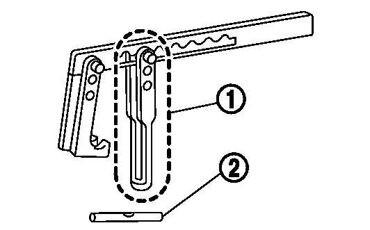
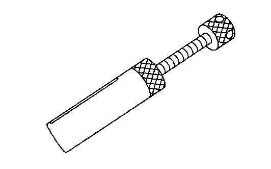
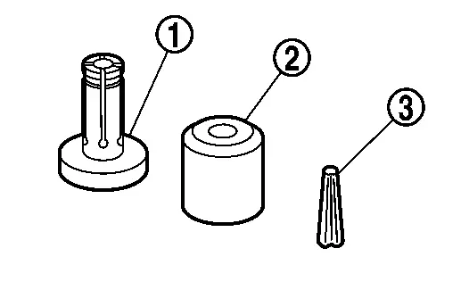
KV10116200 (NI-26336-A) Valve spring compressor 1. KV10115900 (NI-26336-20) Attachment 2.KV10109220 ( — ) Adapter |
| Disassembling valve mechanism Part is a component of KV10116200 (NI-26336-A), but Part is a component of KV10116200 (NI-26336-A), but Part  is not so. is not so. |
KV10107902 (NI-38959) Valve oil seal puller |
| Replacing valve oil seal |
KV10115600 (NI-38958) Valve oil seal drift |
| Installing valve oil seal Use side A
|
EM03470000 (NI-8037) Piston ring compressor |
| Installing piston assembly into cylinder bore |
KV10111100 (NI-37228) Seal cutter |
| Removing oil pan (upper), timing chain case, etc. |
KV10112100 (BT-8653-A) Angle wrench |
| Tightening bolts for connecting rod bearing cap, cylinder head, etc. at an angle |
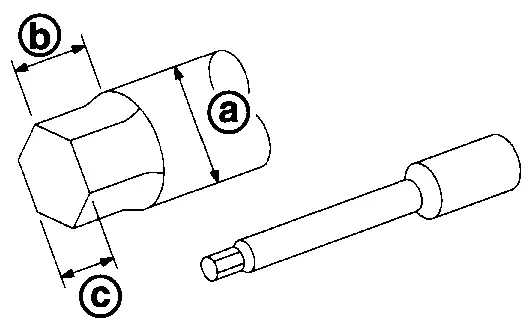
KV10117100 (NI-3647-A) Heated oxygen sensor wrench |
| Loosening or tightening air fuel ratio sensor 1 and heated oxygen sensor For 22 mm (0.87 in) width hexagon nut |
KV10118600 (NI-48641) Ring gear stopper |
| Removing and installing crankshaft pulley |
KV101296S0 ( — ) Direct injection puller |
| Removing and installing fuel injector |
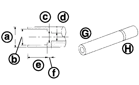
KV10119990 ( — ) Injector seal drift set
|
| Installing fuel injector seal |
ST10120000 (NI-24239-01) Cylinder head bolt wrench |
| Loosening and tightening cylinder head bolt, and used with the angle wrench [SST: KV10112100 (BT-8653-A)]
|
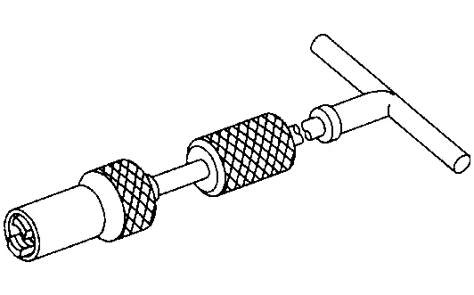
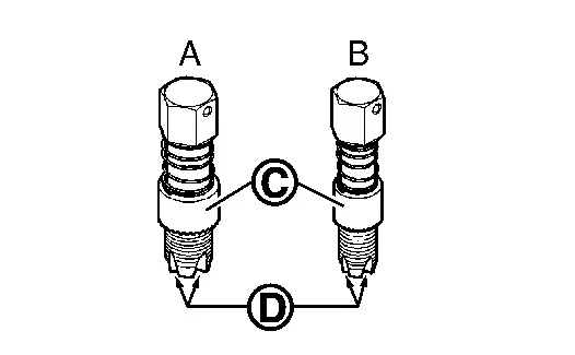
— (NI-43897-18) (NI-43897-12) Oxygen sensor thread cleaner |
| Reconditioning the exhaust system threads before installing a new air fuel ratio sensor and heated oxygen sensor (Use with anti-seize lubricant shown below.) A: NI-43897-18 [18 mm (0.71 in) dia.] for zirconia heated oxygen sensor and air fuel ratio sensor B: NI-43897-12 [12 mm (0.47 in) dia.] for titania heated oxygen sensor
 : Flutes : Flutes |
 .
. : 20 (0.79) dia.
  : 8 (0.31) dia.
 : 13 (0.51) dia.
  : 10.7 (0.421)
 : 10.3 (0.406) dia.
  f: 5 (0.20)
 : side B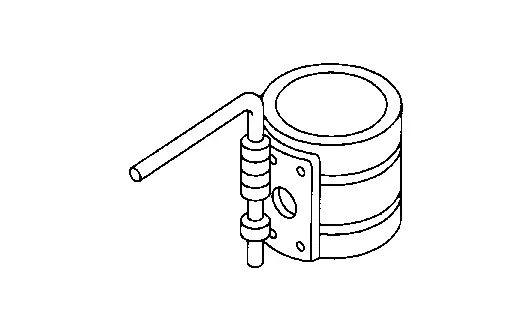
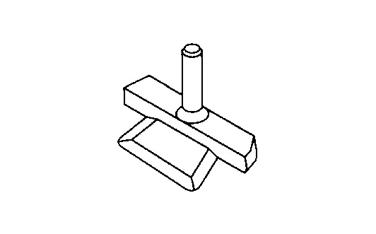
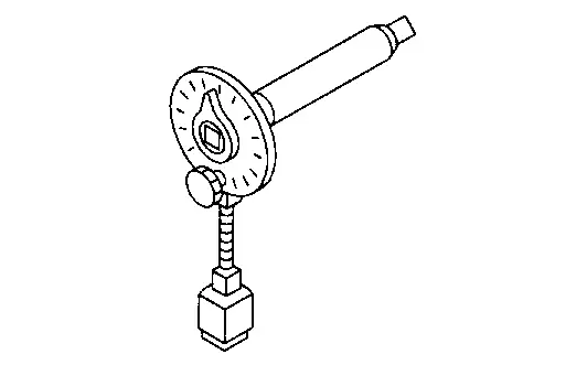
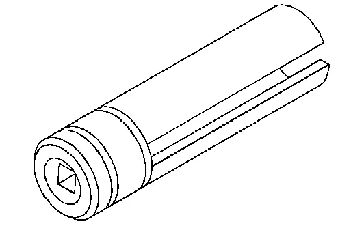
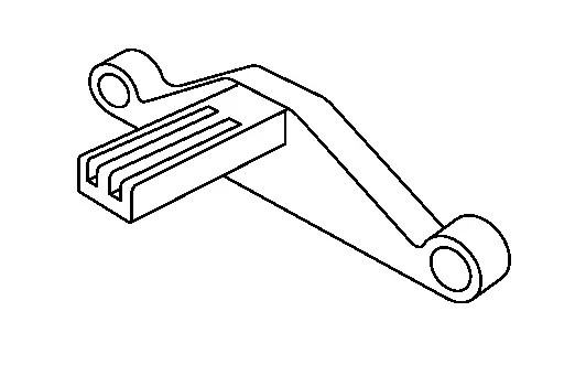
 : Mating surface shave cylinder
 Preparation
...
 Commercial Service Tools or/and Repair Part
Tool name Description Tube presser
Pressing the tube of liquid gasket Power tool
Loosening nuts and bolts TORX socket
Removing and installing drive plate Mobile floor crane
Removing and ...
Other materials:
Work Flow
OVERALL SEQUENCE
DETAILED FLOW
INTERVIEW FOR MALFUNCTION
Interview the symptom to the customer.
>>
GO TO 2.
SYMPTOM CHECK
Check the symptom from the customer's information.
>>
GO TO 3.
FAIL-SAFE ACTIVATION CHECK
Check that the symptom is applied to the fail-safe activation.
Does the ...
Diagnosis Procedure
CHECK RECLINING MECHANISM
Check for the following.
Mechanism deformation or pinched foreign materials.
Interference with other parts because of poor installation.
Is the inspection result normal?
YES>>
GO TO 2.
NO>>
Repair or replace the malfunctioning parts.
CHECK RECLINING SWITCH
Ch ...
Removal and Installation
WARNING:
REMOVAL
Water pipe 1
Remove engine cover. Refer to Removal and Installation.
Drain engine coolant. Refer to ENGINE COOLANT : Draining.
CAUTION:
Perform this step when the engine is cold.
Remove air inlet tube 1. Refer to Removal & Installation.
Remove water hose 2 and water hose 3 fr ...

0.0065