Exploded View
STEERING SHAFT
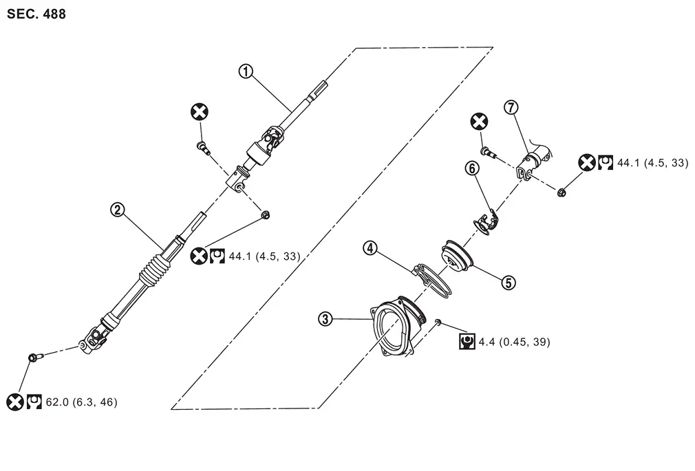
 |
Steering shaft |  |
Lower joint |  |
Hole cover* |
 |
Clamp* |  |
Hole cover seal |  |
Collar |
 |
Upper joint | ||||
| *: Replace and as a set. |
|||||
 : Always replace after every disassembly. : Always replace after every disassembly. |
|||||
 : N·m (kg-m, ft-lb) : N·m (kg-m, ft-lb) |
|||||
 : N·m (kg-m, in-lb) : N·m (kg-m, in-lb) |
|||||
Removal and Installation
WARNING:
-
Jacking up or lift up the vehicle may the vehicle height to go down which cause a personal injury and/or damage to the air suspension component parts. Refer to Precaution for when Jacking and Lifting Up the vehicle with Electronic Air Suspension System.
Removal
CAUTION:
Spiral cable may be cut if steering wheel turns while separating steering column assembly and steering gear assembly. Be sure to secure steering wheel using string to avoid turning.
Set vehicle to the straight-ahead position.
Fix the steering wheel.
Remove driver knee air bag module. Refer to Removal and Installation.
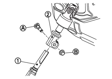
Remove steering shaft fixing bolt  and nut
  , and separate lower joint from steering shaft .
Remove lower joint fixing fixing bolt , and remove lower joint from steering gear assembly .
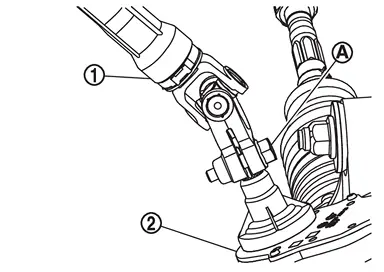
CAUTION:
-
When removing lower joint, never insert a tool, such as a screwdriver, into the yoke groove to pull out the lower joint. In case of the violation of the above, replace lower joint with a new one.
-
Spiral cable may be cut if steering wheel turns while separating steering column assembly and steering gear assembly. Be sure to secure steering wheel using string to avoid turning.
Turn carpet and remove the hole cover mounting nuts.
Remove upper joint fixing bolt and nut , and separate steering shaft from upper joint .
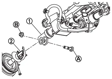
Remove the steering shaft and hole cover assembly.
Remove collar, hole cover seal, and hole cover assembly.
CAUTION:
Never damage hole cover seal.
Perform a post-removal inspection. Refer to Inspection.
Installation
Note the following, and install in the reverse order of removal.
CAUTION:
-
Spiral cable may be cut if steering wheel turns while separating steering column assembly and steering gear assembly. Be sure to secure steering wheel using string to avoid turning.
-
Never reuse steering shaft fixing bolt and nut.
-
Never reuse lower joint fixing fixing bolt.
-
Insert the hole cover seal
into the steering shaft and install it until side of the hole cover seal and side of the hole cover come into contact. 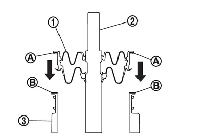
CAUTION:
-
If bellow
of hole cover seal is out of position as shown, push bellow of hole cover seal into design position by hand.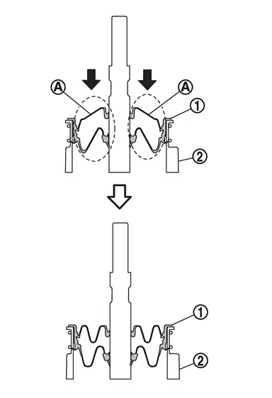
: Hole cover -
Never damage the seal lip of the hole cover seal with the tip of the steering shaft.
-
Install clamp as shown in the figure.
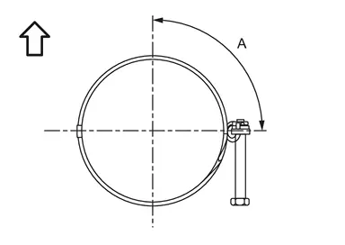
A : 90 degrees : vehicle front -
Tighten the clamp and check the length (A).
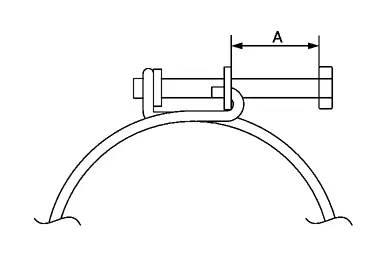
Clamp length (A) : 16 - 20 mm (0. 63 - 0.79 in) -
Insert the collar
into the steering shaft , make sure that the claws of the collar are not half-fitted into the grooves of the steering shaft, and that they are fully seated all the way.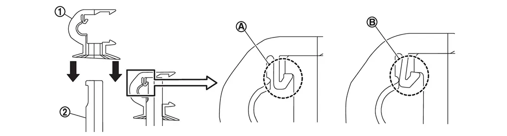
: OK : NG -
After tightening the upper joint fixing bolt
and nut , check the no clearance between steering shaft , bolt and upper joint .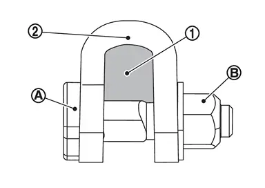
CAUTION:
Never reuse upper joint mounting nut.
-
When installing lower joint, tighten the steering gear side fixing bolt first.
-
When installing the lower joint to steering gear assembly, perform the following procedure.
-
After aligning the blocking phase of pinion, the lower joint
shall be inserted to the pinion shaft of steering gear assembly until lower joint lower surface is in contact with pinion shaft of steering gear assembly surface .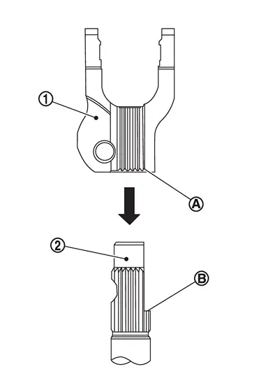
-
Insert bolt
to lower joint , and tighten bolt to the specified torque.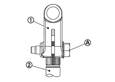
: Pinion shaft of steering gear assembly
CAUTION:
-
Do not insert the bolt from the reverse direction.
-
Be sure to insert the bolt
in the correct position before fastening.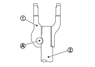
: Lower joint : Pinion shaft of steering gear assembly
-
When installing lower joint
to steering shaft , check the fixing length (A).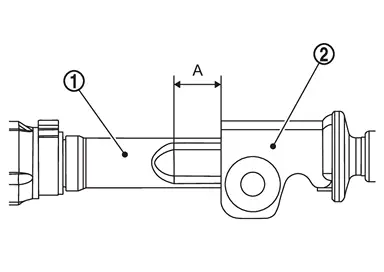
A : 15.9 - 21.9 mm (0.626 - 0.862 in) -
After tightening the steering shaft fixing bolt
and nut , check the no clearance between lower joint , bolt and steering shaft .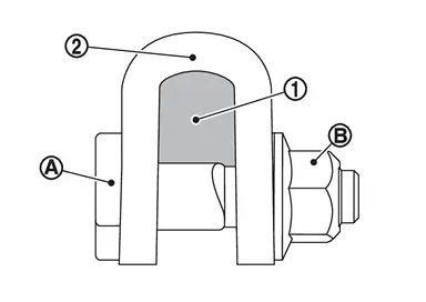
CAUTION:
Never reuse steering shaft mounting nut.
-
Perform a post-installation inspection. Refer to Inspection.
Inspection
INSPECTION AFTER REMOVAL
-
Check dust boot clamp (looseness and disconnection) and dust boot (scratches, cracks, and holes). Replace the lower joint, as necessary.
-
Check each part of lower joint for damage and other malfunctions. Replace if there is a malfunction.
-
Check each part of steering shaft for damage and other malfunctions. Replace if there is a malfunction.
-
Check steering shaft and hole cover seal for scratches, cracks, and holes. Replace the steering shaft or hole cover seal, as necessary.
-
Check the sliding range (A) of the lower joint.
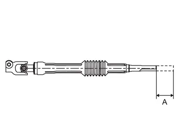
CAUTION:
Check the sliding range (between the extended position and the contracted position) of the lower joint.
| Sliding range (A) | : Refer to Steering Shaft. |
-
Check the length (A) (extended position) of the lower joint.
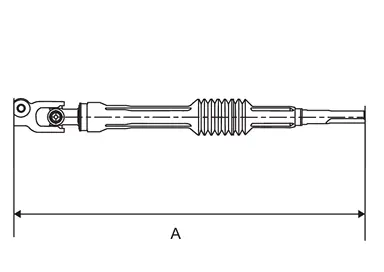
Lower joint length (A) : Refer to Steering Shaft. -
Rotate the steering shaft to check runout of the steering shaft at the runout measuring point
by using dial indicator and V-block. 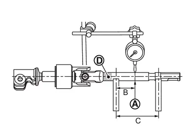
CAUTION:
Never set V-block on black painted part  .
.
| Steering shaft runout | : Refer to Steering Shaft. |
| B | : 37.5 mm (1.476 in) |
| C | : 75 mm (2.95 in) |
INSPECTION AFTER INSTALLATION
-
Check dust boot bellows (deformation, such as dents). Manually rework the bellows, as necessary.
-
Check if steering wheel turns smoothly when it is turned several times fully to the end of the left and right.
-
Check the steering wheel play, neutral position steering wheel, steering wheel turning force, and front wheel turning angle.
-
Adjust neutral position of steering angle sensor. Refer to Work Procedure.
-
If equipped with ProPILOT Assist, perform steering torque calibration after replacing or removal and installation the steering wheel. Refer to Work Procedure.
Other materials
How to use remote keyless entry function
WARNING
In the Nissan Armada, radio frequency signals generated by the Intelligent
Key may interfere with certain medical devices.
Individuals using pacemakers or other electronic medical equipment should
consult the device manufacturer before using the Nissan Armada Intelligent Key.
...
Drive Belt Auto Tensioner and Idler Pulley
Exploded View
Idler pulley
Drive belt auto-tensioner
: N·m (kg-m, ft-lb)
: vehicle front
Removal and Installation
WARNING:
Jacking up or lift up the vehicle may the vehicle height to go down which cause a personal injury and/or damage to the air suspension component parts. ...
Additional Service When Replacing Third Seat Control Unit Lh
Description
When after replacing third seat control unit LH, third seat LH position initialization must be performed. For details, refer to Work Procedure.
Work Procedure
REPLACE THIRD SEAT CONTROL UNIT LH
Replace third seat control unit LH. Refer to Removal and Installation.
>>
GO TO 2.
TH ...