Exploded View
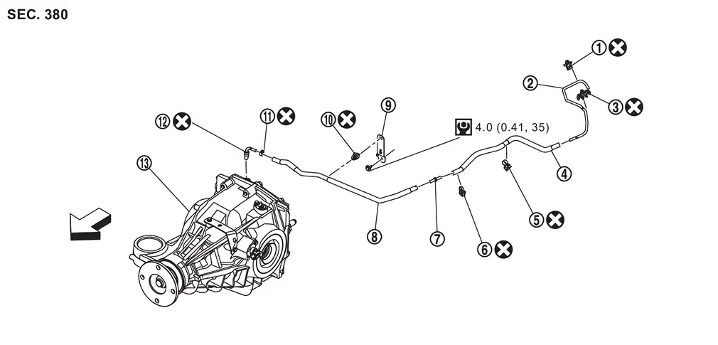
 |
Clip A |  |
Air breather tube |  |
Clip B |
 |
Air breather hose A |  |
Clip C |  |
Clip D |
 |
Hose connector |  |
Air breather hose B |  |
Bracket |
 |
Clip E |  |
Hose clamp |  |
Air breather |
 |
Rear final drive assembly | ||||
| : vehicle front | |||||
 : N·m (kg-m, in-lb) : N·m (kg-m, in-lb) |
|||||
 : Always replace after every disassembly. : Always replace after every disassembly. |
|||||
Removal and Installation
WARNING:
-
Jacking up or lift up the vehicle may the vehicle height to go down which cause a personal injury and/or damage to the air suspension component parts. Refer to Precaution for when Jacking and Lifting Up the vehicle with Electronic Air Suspension System.
REMOVAL
Remove the hose clamp and separate air breather hose B from air breather .
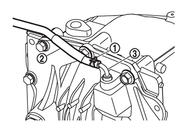
Remove clip E from bracket .
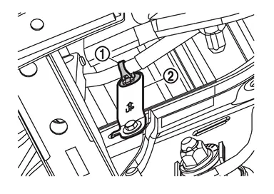
Remove bracket mounting bolt ( ) and remove bracket .
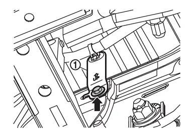
Remove clip D from body frame .
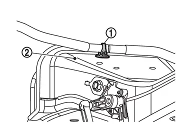
Remove clip C from body frame .
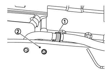
Remove air breather hose A from air breather tube .
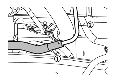
Remove air breather hose assembly.
Remove clip B from bracket .
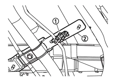
Remove clip A from bracket and remove air breather tube.
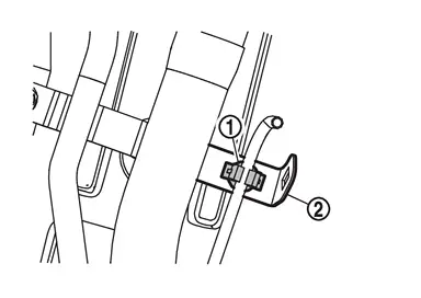
Separate each component part.
INSTALLATION
Note the following, and install in the reverse order of removal.
-
For non-reusable parts, refer to Exploded View.
-
When inserting air breather hose A to air breather tube, align the paint mark
 of air breather hose A with the paint mark
  of breather tube.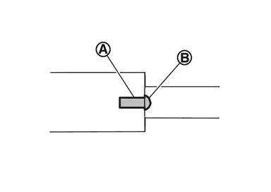
-
When inserting air breather hose to hose connector
, be sure to insert it fully until its end reaches the stop.CAUTION:
Align paint mark
on each air breather hose.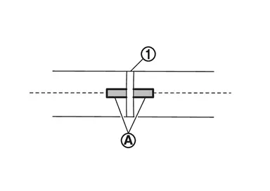
-
When installing air breather to final drive assembly, Install air breather so that the paint mark
on it faced forward of the vehicle.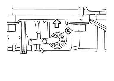
: vehicle front -
When inserting air breather hose B into the air breather, align paint mark
on air breather hose B and tab on the hose clamp with the paint mark on the air breather.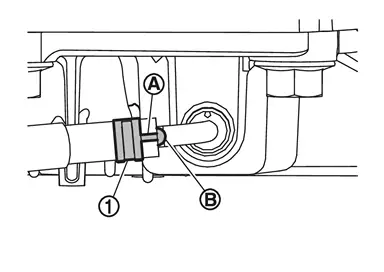
Other materials
VR35DDTT ENGINE MODEL
Basic information
This section outlines the detailed maintenance schedule specifically designed
for the Nissan Armada equipped with the VR35DDTT engine, ensuring long-term durability,
optimal performance, and safe operation under a wide range of driving conditions.
Select the most appropriate ...
Wiper Deicer Does Not Operate
Diagnosis Procedure
CHECK REAR WINDOW DEFOGGER
Check rear window defogger. Refer to Component Function Check.
Is the inspection result normal?
YES>>
GO TO 2.
NO>>
Repair or replace the malfunctioning parts.
CHECK DOOR MIRROR DEFOGGER
Check door mirror defogger. Refer to Component Funct ...
Gps Antenna
Feeder Layout
GPS antenna
AV control unit
Harness connector (M323)
Harness connector (M412)
Clip with connector (M325)
: Clips
To antenna feeder (vehicle side)
Removal & Installation
REMOVALRemove the ins ...