Removal and Installation
CAUTION:
-
Perform work with 2 workers, because it is heavy weight.
-
Support back door with a proper material and use protective tape or shop cloth to protect back door and body from falling and damage when removing and installing back door assembly.
REMOVAL
Remove roof rear garnish. Refer toRemoval and Installation .
Disconnect LH side harness connectors  , and then disengage harness fixing clips.
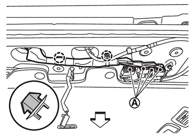
 |
: Clip |
| : vehicle front |
Remove harness grommet from body panel, and then pull out back door harness from vehicle body.
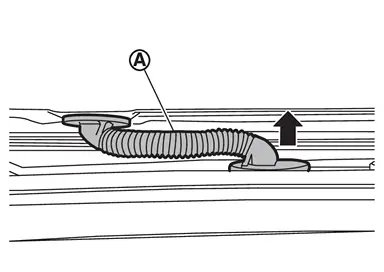
Disconnect rear washer tube B. Refer to Removal and Installation.
Remove washer tube grommet from body panel, and then pull out back door harness from vehicle body.
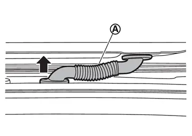
Support back door assembly with the proper material to prevent it from falling.
WARNING:
Injury may occur if door assembly is not supported with a proper material when removing back door assembly.
Remove spindle unit from spindle unit bracket lower (with automatic back door models). Refer to Removal and Installation.
Remove back door stay from back door stay lower bracket (without automatic back door models). Refer to Removal and Installation.
Remove back door hinge mounting nuts, and then remove back door assembly.
INSTALLATION
Note the following items, and then install in the reverse order of removal.
CAUTION:
-
Before installation, apply anticorrosive agent onto mounting surface.
-
When installation, perform the fitting adjustment. Refer to Adjustment.
-
After installation, check whether harness is not pinched. If harness is pinched, pull harness downward lightly.
-
After installation, apply touch-up paint (the body color) onto the head of back door hinge mounting nuts.
-
After installation, check the open/close operation. Refer to Inspection.
-
After installation, apply anticorrosive around the nuts to prevent rust.
Inspection
Open and close the back door. Check that back door hinge rotation portion moves smoothly.
Check back door hinge rotating part for lubrication condition. Apply body grease if necessary.
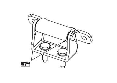
 |
: Body grease |
Adjustment
FITTING ADJUSTMENT
Fitting Adjustment Standard Dimension
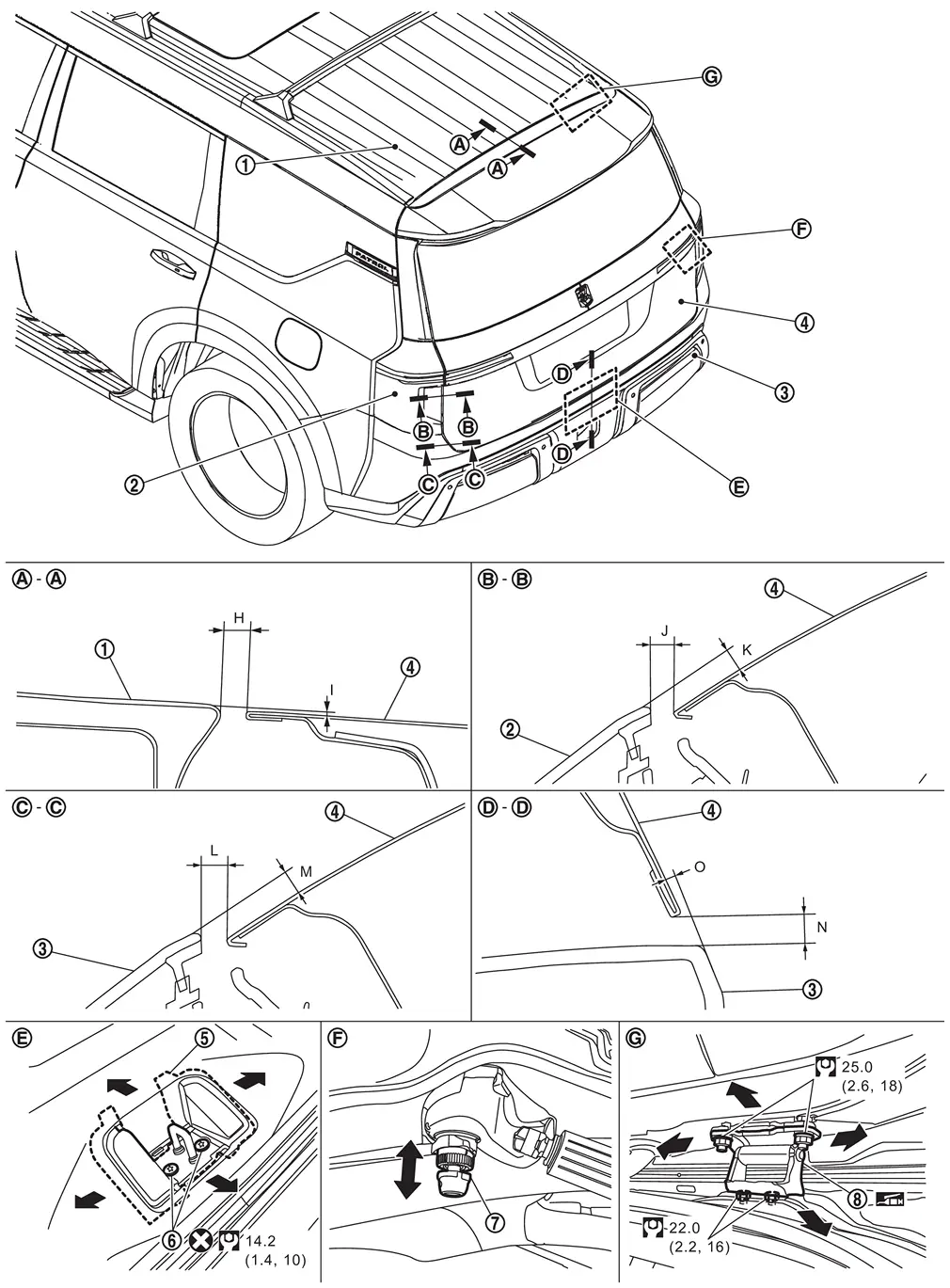
 |
Roof panel |  |
Rear combination lamp |  |
Rear bumper fascia |
 |
Back door panel |  |
Back door striker |  |
TORX bolt |
 |
Back door bumper rubber upper |  |
Back door hinge | ||
 |
: Always replace after every disassembly. | ||||
 |
: N·m (kg-m, ft-lb) | ||||
|
: Body grease | ||||
Unit: mm [in]
| Portion | Standard | Tolerance |
Difference (LH/RH, MAX) | Parallel | ||||
|---|---|---|---|---|---|---|---|---|
| Roof panel – Back door panel | – |
H | Clearance |
6.5 [0.256] |
+ 1.5 [+ 0.059] - 1.0 [- 0.039] |
< 3.0 [0.118] | < 2.0 [0.079] | |
| I | Surface height |
1.0 [0.039] |
± 1.0 [± 0.039] |
— | < 1.5 [0.059] | |||
| Back door panel – Rear combination lamp |  – – |
J | Clearance |
5.0 [0.197] |
± 2.1 [± 0.083] |
< 2.9 [0.114] | < 2.0 [0.079] | |
| K | Surface height |
1.0 - 4.4 [0.039 - 0.173] |
± 2.0 [± 0.079] |
< 2.0 [0.079] | < 2.0 [0.079] | |||
| Back door panel – Rear bumper fascia |  – – |
L | Clearance |
5.0 - 5.3 [0.197 - 0.209] |
± 2.0 [± 0.079] |
< 3.0 [0.118] | < 2.0 [0.079] | |
| M | Surface height |
0.5 - 0.7 [0.020 - 0.028] |
± 2.0 [± 0.079] |
< 2.0 [0.079] | < 2.0 [0.079] | |||
 – – |
N | Clearance |
6.0 [0.236] |
± 2.0 [± 0.079] |
— | < 2.1 [0.083] | ||
| O | Surface height |
0.5 - 1.0 [0.020 - 0.039] |
± 2.0 [± 0.079] |
— | < 2.0 [0.079] | |||
Check the clearance and the surface height between back door and each part by seeing and touching.
If the clearance and the surface height are out of specification, adjust them according to the procedures shown below.
Fitting Adjustment Procedure
Remove back door striker. Refer to Removal and Installation.
Loosen back door hinge mounting bolts of back door side.
Temporarily install back door striker.
CAUTION:
Never reuse TORX bolt. Always replace it with a new one when it is removed.
Adjust the clearance and surface height of back door according to the fitting standard dimension by moving back door assembly and adjusting back door bumper rubber upper.
 NOTE:
NOTE:
-
Adjust the back door bumper rubber upper according to the following procedure.
-
Turn the stopper part
counterclockwise to unlock.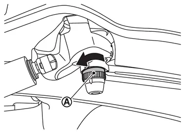
-
Adjust by moving the bumper rubber part
up and down.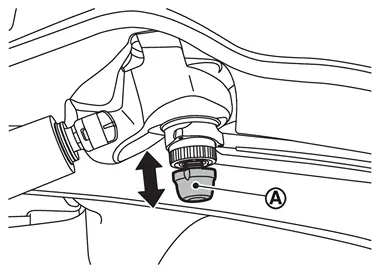
-
Turn the stopper part
clockwise to lock.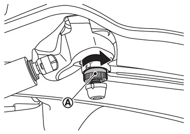
-
-
Back door bumper rubber upper height extends 1.6 mm [0.063 in] automatically when it is locked.
Tighten rear door hinge mounting nuts to the specified torque.
CAUTION:
-
After tightening, apply touch-up paint (the body color) if the paint around hinge and mounting nuts are peeled off during adjustment.
-
Before installation, apply anticorrosive agent onto mounting surface.
Position back door lock assembly and engage back door striker. Check back door lock assembly and back door striker for looseness.
Tighten back door striker mounting TORX bolts to the specified torque.
Install luggage rear plate. Refer to Removal and Installation.
CAUTION:
-
After adjusting, check that bumper rubber is in contact with vehicle body surely.
-
After adjusting, check the open/close operation. Refer to Inspection.
-
After adjusting, perform calibration of automatic back door position information. Refer to Work Procedure.
-
After adjusting, perform the camera calibration. Refer to Work Flow.
BACK DOOR STRIKER ADJUSTMENT
Adjust back door striker so that it becomes parallel with back door lock insertion direction.
Other materials
How to park with predictive course lines
WARNING
If non-standard tire sizes are installed on the Nissan Armada, the predictive
course lines may not display accurately.
On slippery or snow-covered roads, the Nissan Armada predicted path may
differ from the actual vehicle movement.
If the Nissan Armada battery is disconnected o ...
Front Oil Seal
Exploded View
Front output shaft
Front oil seal
Front case
Snap ring
Sprockets with chain
Snap ring
Rear case
Rear companion flange
O-ring
: Always replace after every disassembly.
: N·m (kg-m, ft-lb)
: Apply transfer fluid.
: Apply Genuine Liquid Gas ...
Drain Hose
Exploded View
Refer to Exploded View.
Removal and Installation
REMOVALFrontRemove headlining. Refer to Removal and Installation.
Remove instrument panel assembly. Refer to Removal and Installation.
Remove front drain hose from fixing clips.
Disconnect front drain hose from moonroof unit assembly and ...