Exploded View
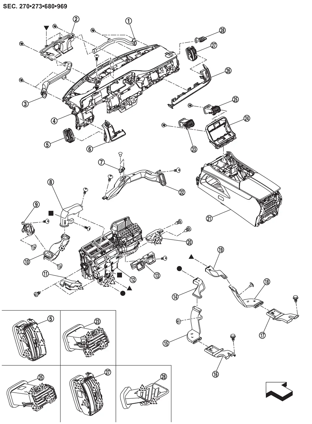
 |
Side defroster nozzle RH |  |
Center defroster nozzle |  |
Side defroster nozzle LH |
 |
Instrument panel assembly |  |
Side ventilator grille LH |  |
Instrument finisher A |
 |
Ionizer (with ionizer models) |
 |
Side ventilator duct 1 LH |  |
Side ventilator duct 3 LH |
 |
Side ventilator duct 2 LH |  |
Front foot duct LH |  |
Front A/C unit assembly |
 |
Center ventilator duct |  |
Rear floor duct 1 LH |  |
Rear floor duct 2 LH |
 |
Rear floor duct 3 LH |  |
Rear floor duct 3 RH |  |
Rear floor duct 2 RH |
 |
Rear floor duct 1 RH |  |
Front foot duct RH |  |
Front center console assembly |
 |
Side ventilator duct RH |  |
Center ventilator grille LH |  |
Front center console switch finisher assembly |
 |
Center ventilator grille RH |  |
Instrument finisher B |  |
Side ventilator grille RH |
 |
Side defroster grille | ||||
 |
: Clip | ||||
 |
: Pawl | ||||
| : vehicle front | |||||
 , , , ,  , ,  : Indicates that the part is connected at points with same symbol in actual vehicle. : Indicates that the part is connected at points with same symbol in actual vehicle. |
|||||
Center Ventilator Grille
Removal and Installation
REMOVAL
CAUTION:
When removing, always use a remover tool that is made of plastic.
Remove front center console switch finisher assembly. Refer to Removal and Installation.
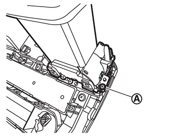
Remove center ventilator grille.Remove fixing screw  .
.
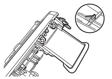
|
: Pawl |
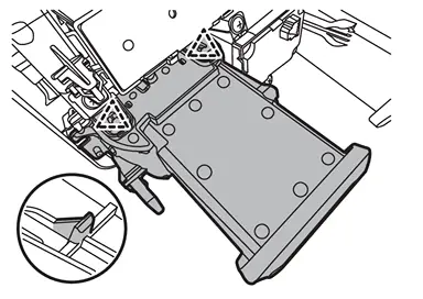
|
: Pawl |
INSTALLATION
Install in the reverse order of removal.
Side Ventilator Grille
Removal and Installation
REMOVAL
CAUTION:
When removing, always use a remover tool that is made of plastic.
Side Ventilator Grille LH
Remove instrument finisher A. Refer to Removal and Installation.
Remove side ventilator grille LH.Disengage fixing pawls.
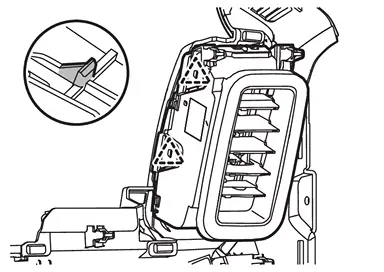
|
: Pawl |
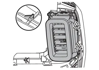
|
: Pawl |
Side Ventilator Grille RH
Remove instrument finisher B. Refer to Removal and Installation.
Remove side ventilator grille RH.Disengage fixing pawls.
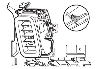
|
: Pawl |
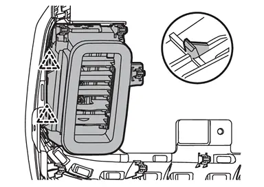
|
: Pawl |
INSTALLATION
Install in the reverse order of removal.
Center Ventilator Duct
Removal and Installation
REMOVAL
Remove instrument panel assembly. Refer to Removal and Installation.
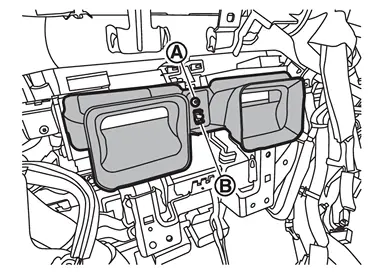
Remove fixing screw and disengage fixing pawl  , and then remove center ventilator duct.
INSTALLATION
Install in the reverse order of removal.
Side Ventilator Duct
Removal and Installation
REMOVAL
Remove instrument lower panel LH and steering column cover lower. Refer to Removal and Installation.
Remove driver knee air bag module (if equipped). Refer to Removal and Installation.
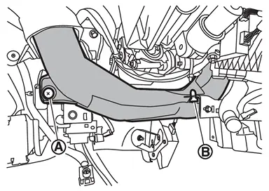
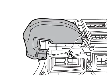
Remove fixing clips and , and then remove side ventilator duct 2 LH.
Remove instrument finisher A. Refer to Removal and Installation.
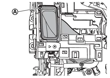
Remove fixing screw and clip , and then remove side ventilator duct 3 LH.
Remove instrument panel from steering member. Refer to Removal and Installation.
Remove ionizer (with ionizer models).
Remove ADAS control unit 2. Refer to Removal and Installation (without ProPILOT assist 2.1 models) or Removal and Installation (with ProPILOT assist 2.1 models).
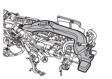
Remove fixing screws , and then remove side ventilator duct RH.
Remove front A/C unit assembly from steering member. Refer to Removal and Installation.
Remove fixing screws , and then remove side ventilator duct 1 LH.
INSTALLATION
Install in the reverse order of removal.
Side Defroster Nozzle
Removal and Installation
REMOVAL
Remove instrument panel assembly from steering member. Refer to Removal and Installation.
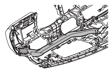
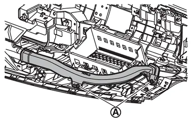
Remove fixing screws , and then remove side defroster nozzle.
-
Side defroster nozzle LH
-
Side defroster nozzle RH
INSTALLATION
Install in the reverse order of removal.
Side Defroster Grille
Removal and Installation
REMOVAL
Remove instrument panel assembly. Refer to Removal and Installation.
Remove side defroster nozzle RH. Refer to Removal and Installation.
Disengage fixing pawls from reverse side of instrument panel assembly, and then remove side defroster grille.
INSTALLATION
Install in the reverse order of removal.
Center Defroster Nozzle
Removal and Installation
REMOVAL
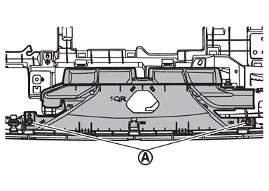
Remove side defroster nozzle LH and RH. Refer to Removal and Installation.
Remove fixing screws .
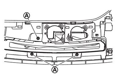
Remove fixing screws , and then remove center defroster nozzle.
INSTALLATION
Install in the reverse order of removal.
Front Foot Duct
Removal and Installation
REMOVAL
Front Foot Duct LH
Remove instrument lower panel LH and center instrument lower panel. Refer to Removal and Installation.
Remove front center console switch finisher assembly. Refer to Removal and Installation.
Remove driver knee air bag module. Refer to Removal and Installation.
Remove side ventilator duct 2 LH. Refer to Removal and Installation.
Remove fixing screws and disengage fixing pawl, and then remove front foot duct LH.
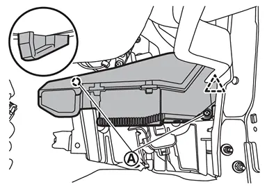
|
: Pawl |
Front Foot Duct RH
Remove passenger knee air bag module. Refer to Removal and Installation.
Remove instrument pad D. Refer to Removal and Installation.
Remove fixing screws and disengage fixing pawl, and then remove front foot duct RH.
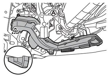
|
: Pawl |
INSTALLATION
Install in the reverse order of removal.
Rear Floor Duct
Removal and Installation
REMOVAL
Remove front center console body assembly. Refer to Removal and Installation.
Disengage fixing pawls, and then remove rear floor duct LH 1 and RH 1 .
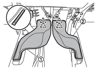
|
: Pawl |
Peel off front floor carpet to secure work space. Refer to Removal and Installation.
Remove fixing clip , and then remove rear floor duct 2.
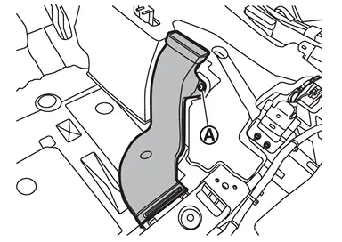
Remove mounting screw and disengage harness fixing clip, and then remove rear floor duct 3.
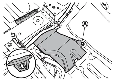
|
: Clip |
INSTALLATION
Install in the reverse order of removal.
Other materials
Normal Operating Condition
Description
FRONT WIPER MOTOR PROTECTION FUNCTION
The CPU integrated in the front wiper motor may stop the front wiper to protect the front wiper motor if any obstruction (operation resistance) such as a large amount of snow is detected during the front wiper operation.
At that time turn OFF the ...
Rear Wiper
Exploded View
Rear wiper motor
Rear wiper blade
Rear wiper arm
Pivot seal
: N·m (kg-m, in-lb)
Rear Wiper Arm
Removal and Installation
CAUTION:
Clean back door window glass and rear wiper refill so that back door window glass may not be damaged by dust, ...
Precautions
Precaution for Supplemental Restraint System (SRS) "AIR BAG" and "SEAT BELT PRE-TENSIONER"
The Supplemental Restraint System such as “AIR BAG� and “SEAT BELT PRE-TENSIONER�, used along with a front seat belt, helps to reduce the risk or severity of injury to the driver and front passenger fo ...