Exploded View
REMOVAL
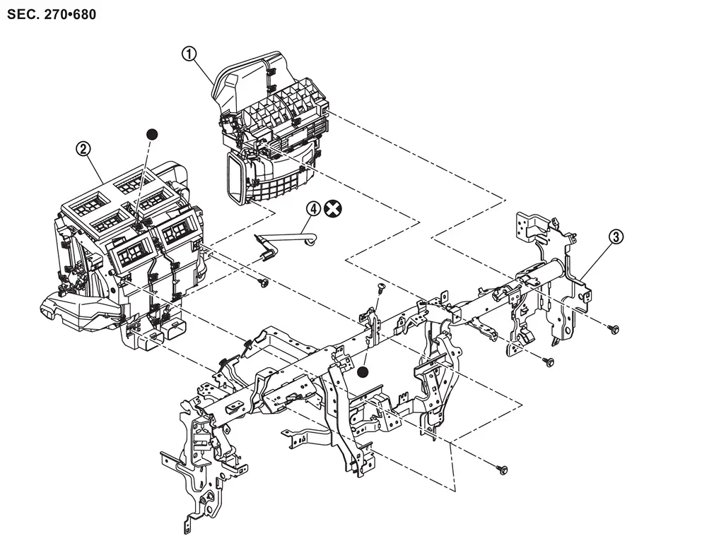
 |
Front blower unit assembly |  |
Front heater & cooling unit assembly |  |
Steering member |
 |
Drain hose | ||||
 |
: Always replace after every disassembly. | ||||
 : Indicates that the part is connected at points with same symbol in actual vehicle. : Indicates that the part is connected at points with same symbol in actual vehicle. |
|||||
DISASSEMBLY
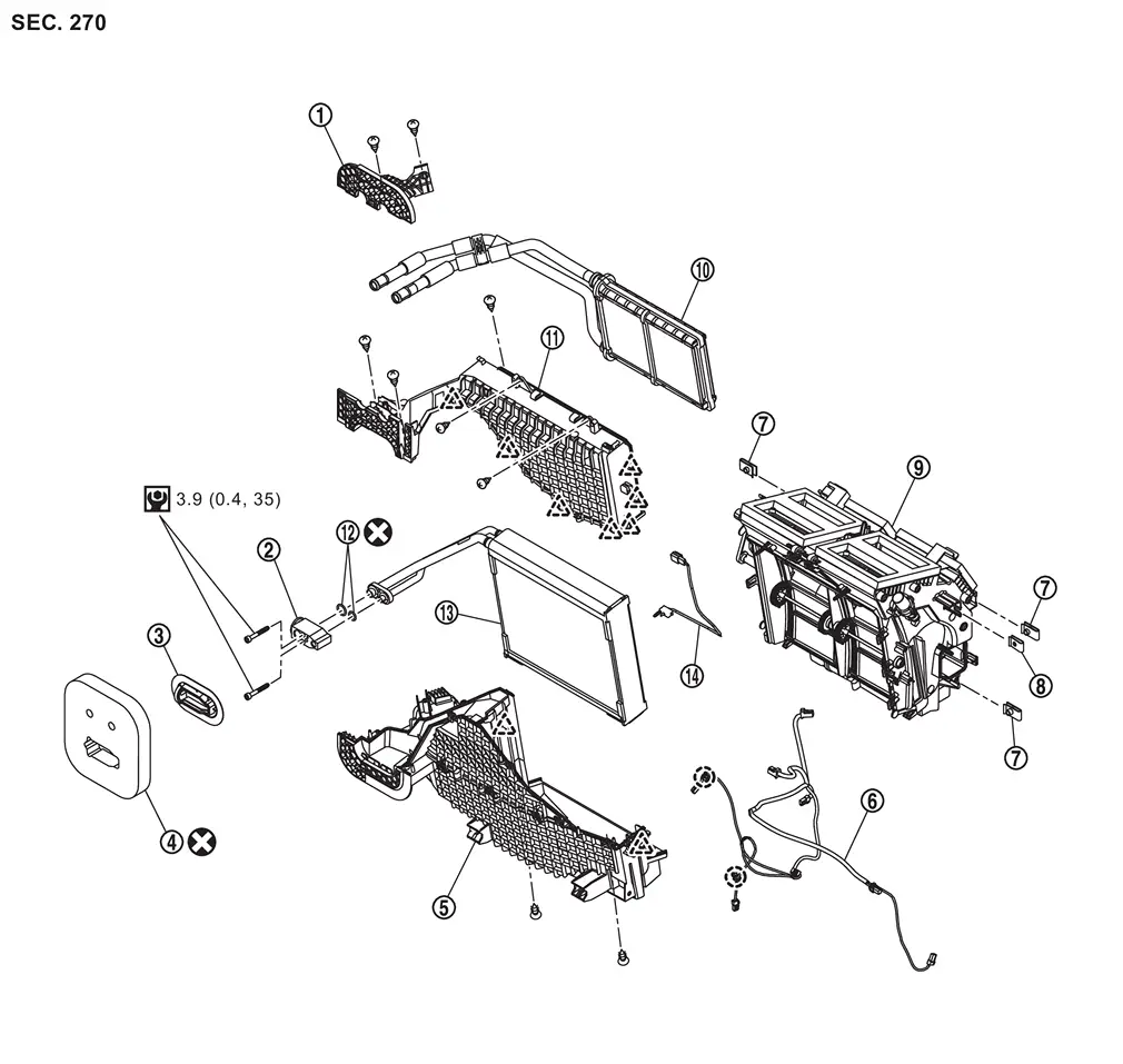
|
Heater pipe support | |
Front expansion valve | |
Cooler grommet |
|
Cooler packing |  |
Front case lower assembly |  |
Sub harness |
 |
J nut |  |
Spring nut |  |
Front heater & cooling unit |
 |
Front heater core |  |
Front case upper |  |
O-ring |
 |
Front evaporator |  |
Intake sensor | ||
 |
: Clip | ||||
 |
: Pawl | ||||
|
: Always replace after every disassembly. | ||||
 |
: N·m (kg-m, in-lb) | ||||
Front Heater & Cooling Unit Assembly
Removal and Installation
REMOVAL
CAUTION:
-
Perform lubricant return operation before each refrigeration system disassembly. However, if a large amount of refrigerant or lubricant leak is detected, never perform lubricant return operation. Refer to Perform Lubricant Return Operation.
-
When disconnect the A/C piping related parts, cap or wrap the joint of those parts with suitable material such as vinyl tape to avoid the entry of air.
Use a refrigerant collecting equipment (for HFO-1234yf) to discharge the refrigerant. Refer to Recycle Refrigerant.
Drain engine coolant from cooling system. Refer to ENGINE COOLANT : Draining.
Disconnect front heater pipe assembly from front heater core. Refer to Removal and Installation.
Disconnect low-pressure pipe from front expansion valve. Refer to Removal and Installation.
Disconnect high-pressure pipe from front expansion valve. Refer to Removal and Installation.
Remove instrument panel assembly and steering member as a set. Refer to Removal and Installation.
Remove instrument panel assembly from steering member. Refer to Removal and Installation.
Remove each duct.
-
Side ventilator duct (RH and 2 LH). Refer to Removal and Installation.
-
Center ventilator duct. Refer to Removal and Installation.
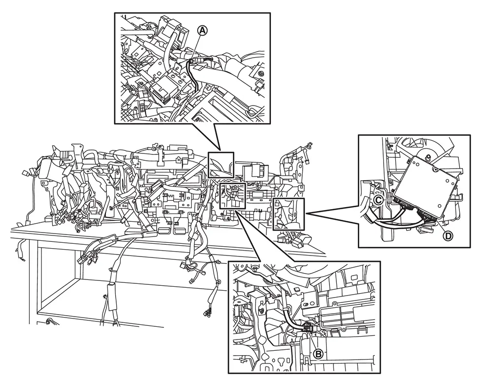
Disconnect harness connectors  ,
,  ,
,  , and
, and  .
.
Remove front heater & cooling unit assembly fixing screw .
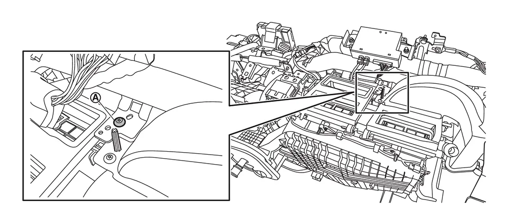
Remove front heater & cooling unit mounting bolts and front blower unit mounting bolts .
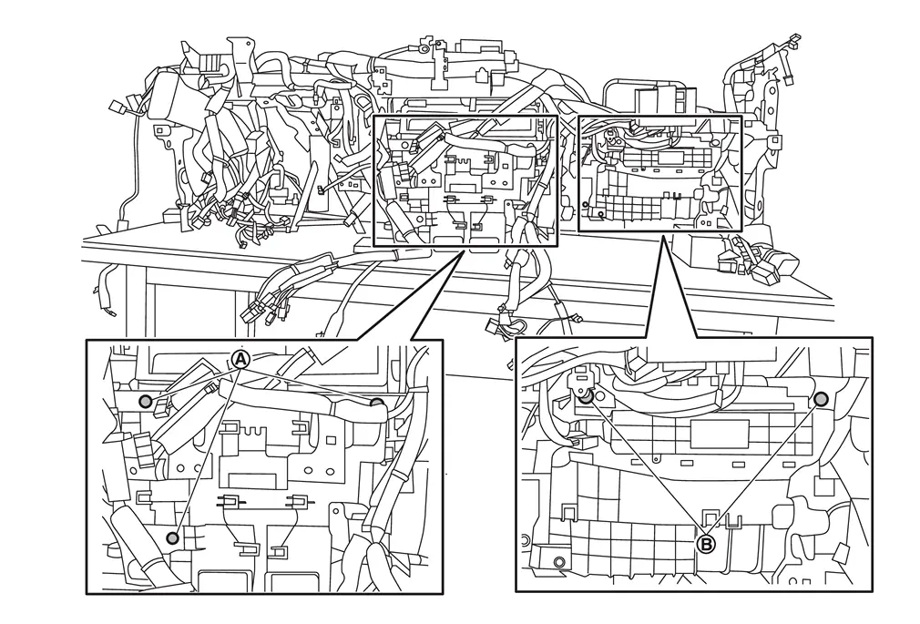
Remove front heater & cooling unit assembly and front blower unit assembly as a set.
CAUTION:
When removing front heater & cooling unit assembly, 2 workers are required to prevent it from dropping.
Remove each duct from front heater & cooling unit assembly.
-
Side ventilator duct 1 LH. Refer to Removal and Installation.
-
Front foot duct (RH and LH). Refer to Removal and Installation.
Remove front blower unit assembly from front heater & cooling unit assembly. Refer to Removal and Installation.
INSTALLATION
Note the following items, and then install in the reverse order of removal.
CAUTION:
-
Use a refrigerant collecting equipment (for HFO-1234yf) to charge the refrigerant. Refer to Charge Refrigerant.
-
Perform a check for refrigerant leakage when charging with refrigerant. Refer to Leak Test.
 NOTE:
NOTE:
When filling radiator with engine coolant. Refer to ENGINE COOLANT : Refilling.
Front Evaporator
Removal and Installation
REMOVAL
Remove front heater & cooling unit assembly. Refer to Removal and Installation.
Remove front heater core. Refer to Removal and Installation.
Remove front expansion valve. Refer to Removal and Installation.
Disconnect front mode door motor harness connector .
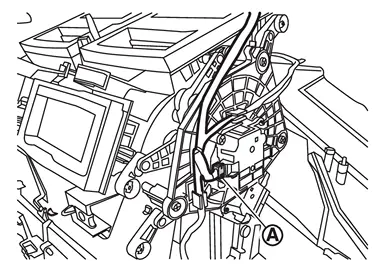
Remove sub harness from front heater & cooling unit.
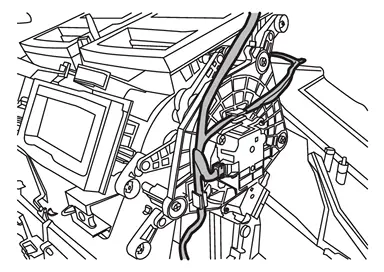
Disconnect front air mix door motor (driver side) harness connector .
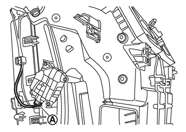
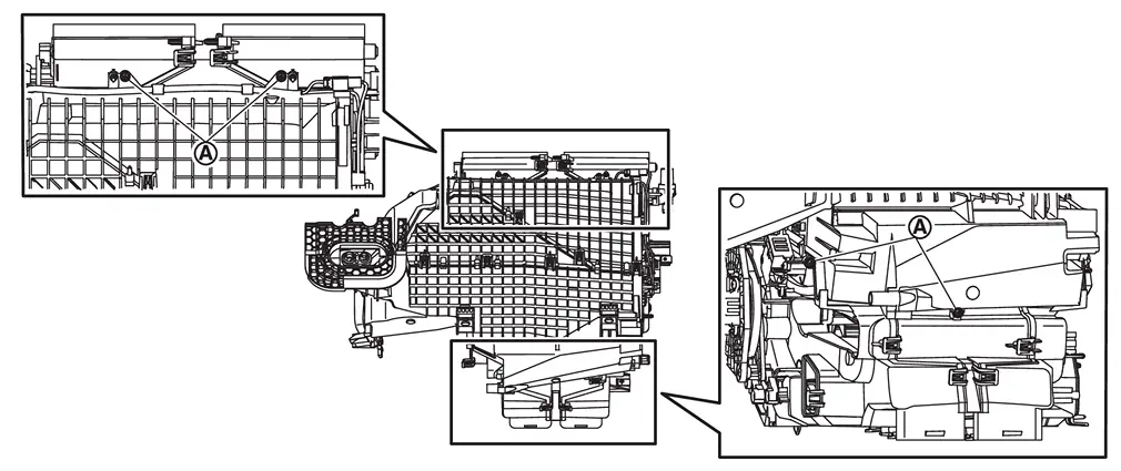
Remove front heater & cooling unit fixing screws .
Disengage fixing pawls, and then remove front heater & cooling unit from front case assembly.
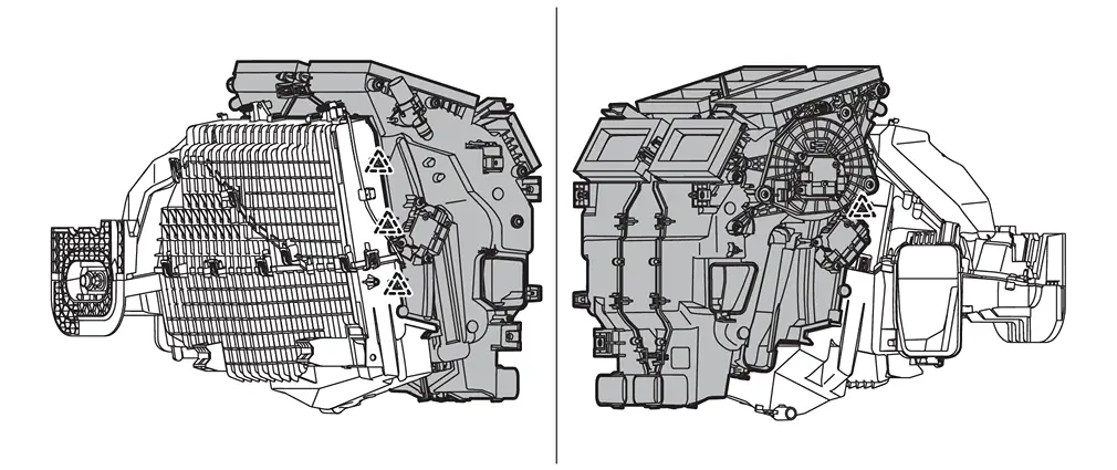
|
: Pawl |
Remove intake sensor from front evaporator. Refer to Removal and Installation.
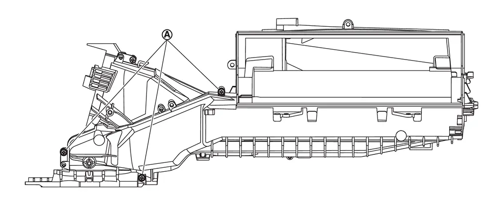
Remove front case upper fixing screws .
Disengage fixing pawls, and then remove front case upper from front case lower assembly.
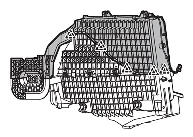
|
: Pawl |
Remove front evaporator from front case lower assembly.
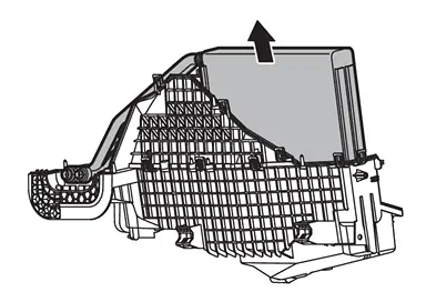
INSTALLATION
Note the following items, and then install in the reverse order of removal.
CAUTION:
-
The air conditioning evaporator should never be repaired or replaced with a part from another vehicle. To replace a damaged or leaking evaporator, use only a new genuine NISSAN replacement part or equivalent.
-
After installing a new evaporator, adjust the compressor lubricant level. Refer to Lubricant Adjusting Procedure for Components Replacement Except A/C compressor.
-
Perform a check for refrigerant leakage when charging with refrigerant. Refer to Leak Test.
NOTE:
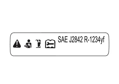
This label indicates that the evaporator complies with SAE J2842.
Front Expansion Valve
Removal and Installation
REMOVAL
CAUTION:
When disconnect the A/C piping related parts, cap or wrap the joint of those parts with suitable material such as vinyl tape to avoid the entry of air.
Remove front heater & cooling unit assembly. Refer to Removal and Installation.
Remove cooler packing.
Remove cooler grommet.
Remove mounting bolts, and then remove front expansion valve.
INSTALLATION
Note the following items, and then install in the reverse order of removal.
CAUTION:
-
To prevent leakage of refrigerant, replace the O-ring with a new one. Apply a coat of compressor oil to the O-ring prior to installation.
-
Replace cooler packing with new one.
-
Perform a check for refrigerant leakage when charging with refrigerant. Refer to Leak Test.
Front Heater Core
Removal and Installation
REMOVAL
Remove front heater & cooling unit assembly. Refer to Removal and Installation.
Disconnect front air mix door motor (passenger side) harness connector .
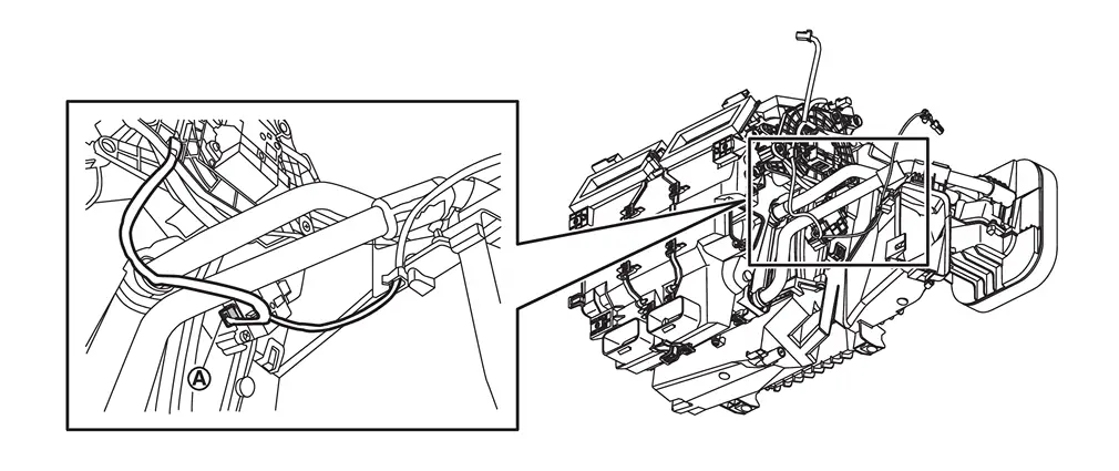
Remove sub harness from front case lower assembly.
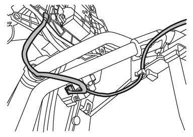
Remove cooler packing.
Remove fixing screws , and then remove heater pipe support.
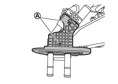
Remove front heater core.
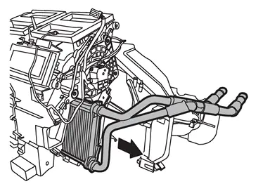
INSTALLATION
Note the following item, and then install in the reverse order of removal.
CAUTION:
Replace cooler packing with new one.
Other materials
Additional Service When Replacing Control Valve & Tcm
Description
WARNING:
Jacking up or lift up the vehicle may the vehicle height to go down which cause a personal injury and/or damage to the air suspension component parts. Refer to Precaution for when Jacking and Lifting Up the vehicle with Electronic Air Suspension System.
When replacing the ...
Noise, Vibration and Harshness (nvh) Troubleshooting
NVH Troubleshooting Chart
Use the chart below to find the cause of the symptom. If necessary, repair or replace these parts. Possible cause and SUSPECTED PARTS Symptom Reference
BRAKE
Noise Shake Shimmy, Judder
Pads damaged
×
—
—
FRONT DISC BRAKE: Inspection and Adjustment
...
Rear Door Assembly
Removal and Installation
CAUTION:
Perform work with 2 workers, because it is heavy weight.
Support door with a proper material and use protective tape or shop cloth to protect door and body from falling and damage when removing and installing door assembly.
REMOVALRemove rear door harness gromm ...