Diagnosis and Repair Work Flow
Work Flow
OVERALL SEQUENCE
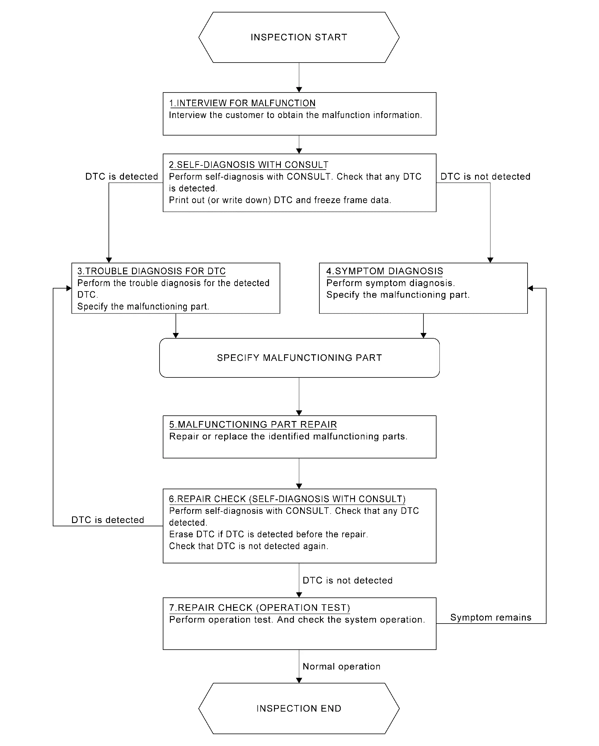
DETAILED FLOW
INTERVIEW FOR MALFUNCTION
It is also important to clarify the customer concerns before starting the inspection. Interview the customer about the concerns carefully and understand the symptoms fully.
 NOTE:
NOTE:
The customers are not professionals. Never assume that “maybe the customer means···� or “maybe the customer mentioned this symptom�.
>>
GO TO 2.
SELF-DIAGNOSIS WITH CONSULT
With CONSULT
Perform self-diagnosis of "Head Up Display� using CONSULT. Refer to CONSULT Function.
NOTE:
Skip to step 4 of the diagnosis procedure if "Head Up Display� is not displayed.
Is any DTC detected?
YES>>GO TO 3.
NO>>GO TO 4.
TROUBLE DIAGNOSIS FOR DTC
-
Check the DTC indicated in the “Self Diagnostic Result�.
-
When DTC is detected, follow the instructions below:
-
Record DTC
-
Freeze Frame Data (FFD)
-
-
Perform the relevant diagnosis referring to the DTC Index. Refer to DTC Index.
>>
GO TO 5.
SYMPTOM DIAGNOSIS
Perform the applicable diagnosis according to the diagnosis chart by symptom. Refer to Symptom Table.
>>
GO TO 5.
MALFUNCTIONING PART REPAIR
Repair or replace the identified malfunctioning parts.
>>
GO TO 6.
REPAIR CHECK (SELF-DIAGNOSIS WITH CONSULT)
With CONSULT
-
Erases self-diagnosis results.
-
Perform self-diagnosis of "Head Up Display� again after repairing or replacing the specific items.
-
Check if any DTC is detected in self-diagnosis results of "Head Up Display� .
Is any DTC detected?
YES>>GO TO 3.
NO>>GO TO 7.
REPAIR CHECK (OPERATION TEST)
Perform operation test. Check that the malfunction symptom is solved or no other symptoms occur.
Is there a malfunction symptom?
YES>>GO TO 4.
NO>>INSPECTION END
Additional Service When Replacing Head up Display Unit
Work Procedure
Description
When replacing or removing the Head Up Display unit, distortion calibration of the display and adjustment of the display position are required.
Work Procedure
REPLACE HEAD UP DISPLAY UNIT
Replace Head Up Display unit. Refer to Removal and Installation.
>>
GO TO 2.
PERFORM CALIBRATION
Perform Head Up Display calibration. Refer to Work Procedure.
>>
GO TO 3.
ADJUST DISPLAY SCREEN
Adjust display screen position. Refer to Switch Name and Function.
>>
GO TO 4.
OPERATION CHECK
Check the display of Head Up Display.
Is the displayed normal?
YES>>WORK END
NO>>Perform display adjustment again. GO TO 3.
Head up Display Calibration
Work Procedure
Description
Calibration must be performed after replacing or removing/installing the following parts..
-
Head Up Display unit
-
Windshield glass
-
Steering member
Diagnosis Procedure
NOTE:
-
Place the vehicle on level ground.
-
Keep the space when calibration. (vehicle front area)
-
Wide: 2.0 m (6.56 ft)
-
Height: 2.0 m (6.56 ft)
-
Length: 2.0 m (6.56 ft)
-
TARGET PREPARATION
Prepare the distortion calibration jig according to the following procedure and the figure.
-
Prepare target sheet according to the figure.
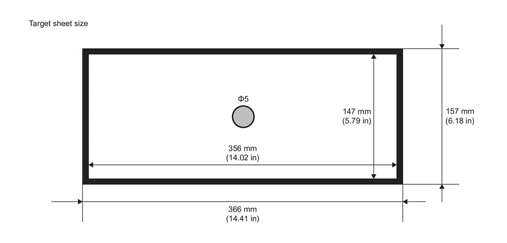
-
Paste the created target sheet onto the board according to the figure.
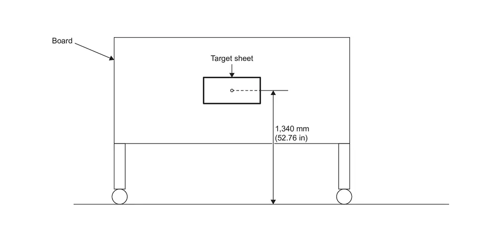
>>
GO TO 2.
TARGET SETTING
-
Mark points “A�, “B�, “C� and “D� at the center position of each wheels.
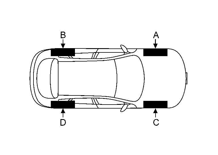
-
Draw line "LH (RH)" passing through points "A (C)" and "B (D)" on the left (right) side of vehicle.
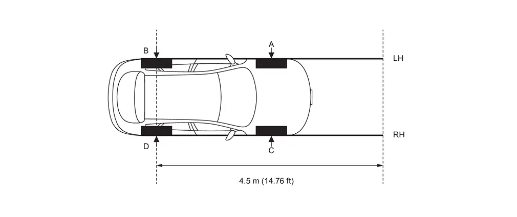 NOTE:
NOTE:
Approximately 4.5 m (14.76 ft) or more from the point "B (D)".
-
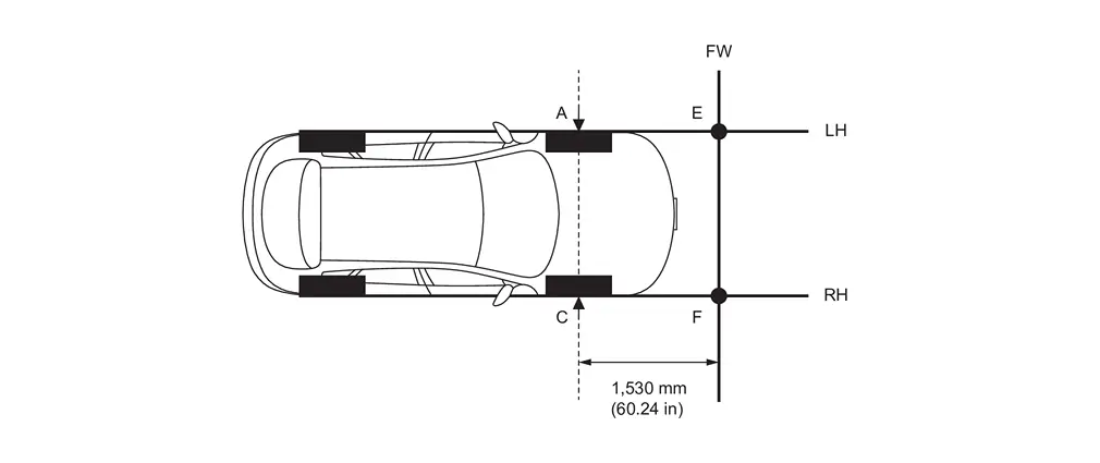
Mark point "E (F)" on the line "LH (RH)" at the positions 1,530 mm (60.24 in) from point "A (C)". And then draw line "FW" passing through the points "E" and "F".
-
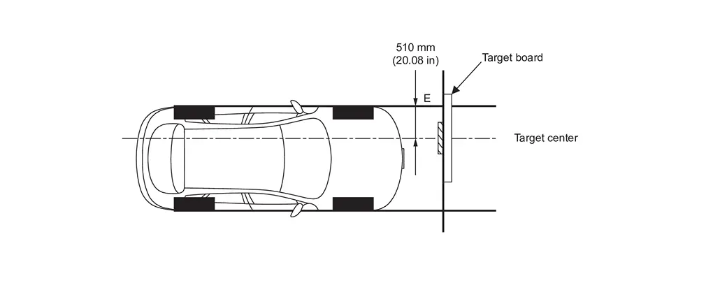
Place the target board on the line "FW" so that the center of the target comes to 510 mm (20.08 in) from mark point "E".
>>
GO TO 3.
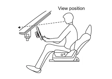
DRIVER'S SEAT POSITION ADJUSTMENT
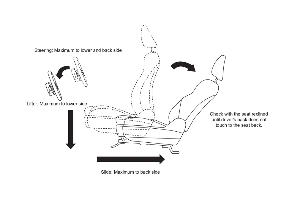
Adjust the driver's seat and steering wheel to the position shown in the figure.
>>
GO TO 4.
RESET OPERATION
-
Turn ignition switch ON.
-
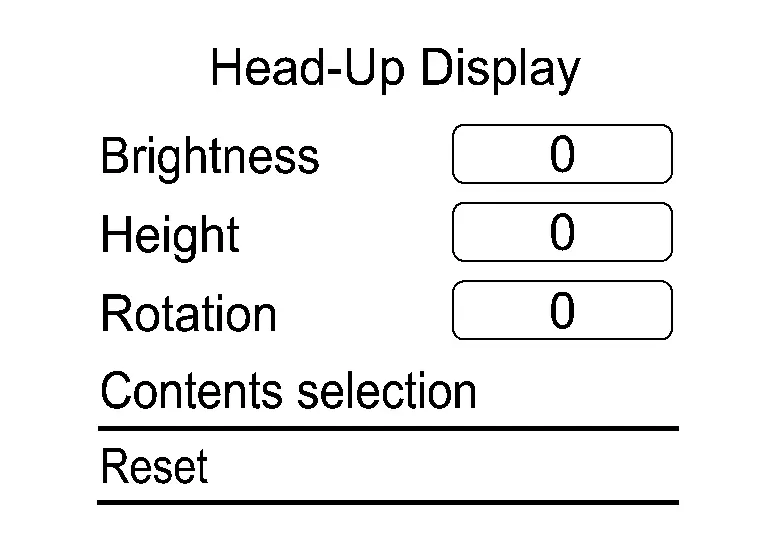
Touch "Reset" on the Head Up Display setting screen of the combination meter and reset the setting. Refer to Switch Name and Function.
>>
GO TO 5.
TARGET CENTER POSITION ADJUSTMENT
With CONSULT
-
Select "Distortion calibration" of "Work Support" on "Head Up Display� using CONSULT.
-
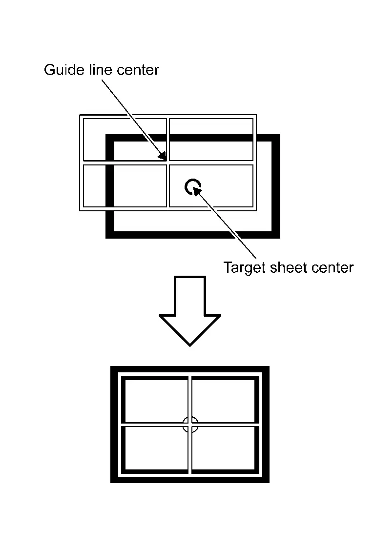
Confirm from the driver's seat whether the center position of the displayed guideline is coincident with the center position of the target sheet.
NOTE:
If there is a gap between the center of the guideline and the target sheet,do not change the vehicle position, and match the center point by moving the target seat and target seat up and down, back and forth with setting the design standard dimension as a basic point.
>>
GO TO 6.
PERFORM DISTORTION CALIBRATION
With CONSULT
-
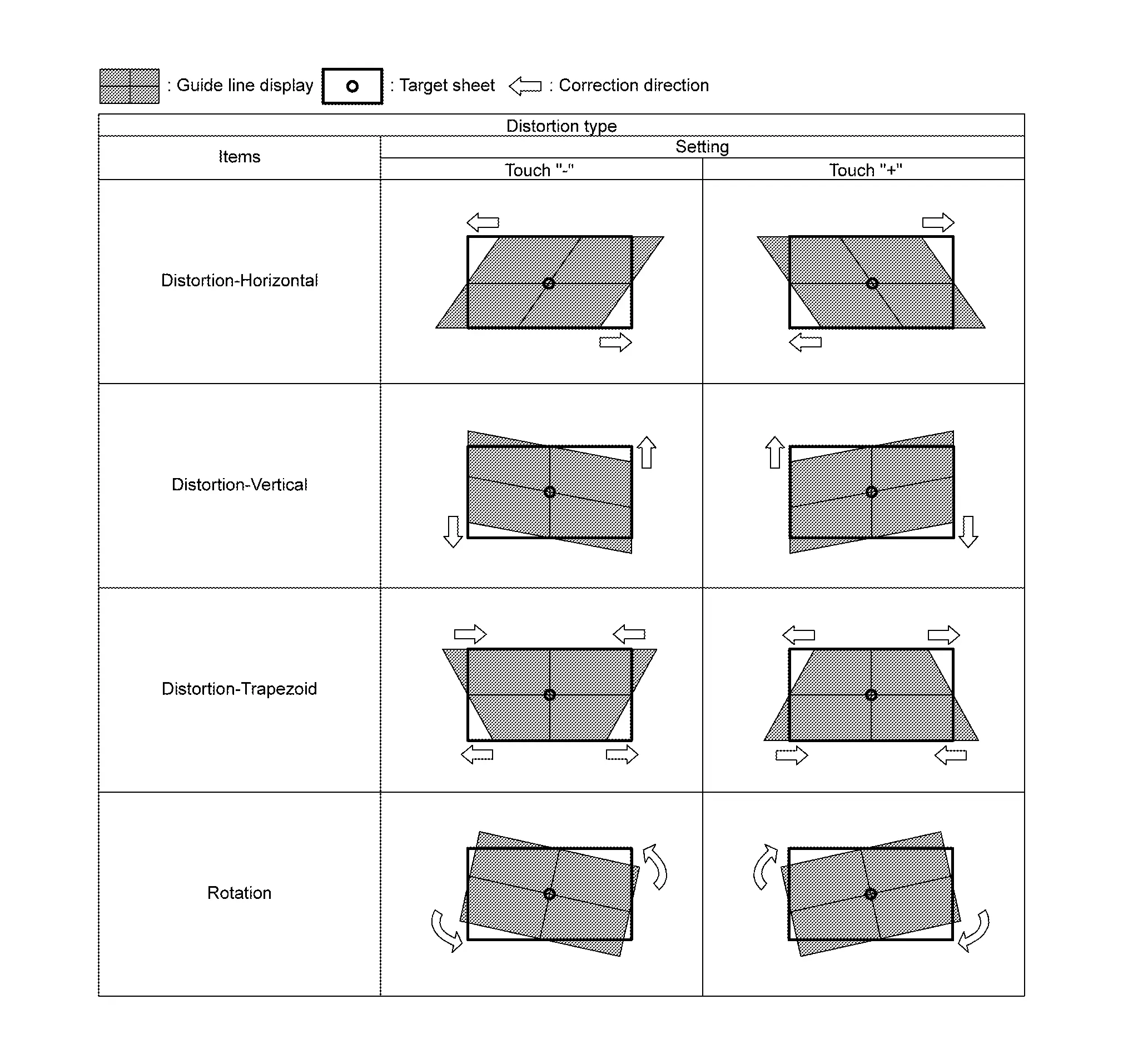
Visually check for the distortion of the guideline from the standard HUD design view-point (Refer to 5-2).

-
If the guideline display is distorted, touch "+" or "-" of the item corresponding to the distortion type to be corrected according to following table, and calibrate to match the target sheet.
-
Touch "Save" and save the setting when calibration is completed.
NOTE:
Touch "Reset" to cancel the change.
>>
WORK END
Other materials
Towing your vehicle
Basic information
When towing a Nissan Armada, it is essential to comply with all applicable local
and regional regulations. Using incorrect towing methods or equipment can lead to
serious vehicle damage.
For safe and proper towing, it is highly recommended that a professional towing
service ...
Noise, Vibration and Harshness (nvh) Troubleshooting
NVH Troubleshooting Chart
Use the chart below to find the cause of the symptom. If necessary, repair or replace these parts. Possible cause and SUSPECTED PARTS Symptom Reference
Vibration Shake Noise
Uneven rotating torque
×
×
Inspection
Center bearing improper installation
× ...
Parking Brake Switch
Removal and Installation
REMOVALRemove the instrument lower panel LH. Refer to Removal and Installation.
Remove parking brake switch mounting screws , and then remove parking brake switch .
: Instrument lower panel LH
INSTALLATIONInstall in the reverse order of removal. ...