Description
MAINTENANCE OF LUBRICANT LEVEL
The compressor lubricant is circulating in the system together with the refrigerant. It is necessary to fill A/C compressor with lubricant when replacing A/C system parts or when a large amount of refrigerant leakage is detected. It is important to always maintain lubricant level within the specified level. Or otherwise, the following conditions may occur.
-
Insufficient lubricant amount: Stuck A/C compressor
-
Excessive lubricant amount: Insufficient cooling (caused by insufficient heat exchange)
| Name | : Refer to Lubricant. |
Inspection
If a A/C compressor is malfunctioning (internal noise, insufficient cooling), check the compressor oil.
COMPRESSOR OIL JUDGMENT
-
Remove the A/C compressor. Refer to Removal and Installation.
-
Sample a compressor oil and judge on the figure.
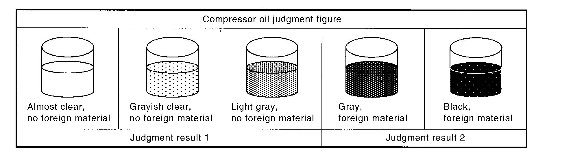
Judgement result 1
Replace A/C compressor only.
Judgement result 2
Replace A/C compressor and condenser & liquid tank.
Perform Lubricant Return Operation
CAUTION:
If a large amount of refrigerant or lubricant leakage is detected, never perform lubricant return operation.
Start the engine and set to the following conditions.
-
Engine speed: Idling to 1,200 rpm
-
A/C switch: ON
-
Fan (blower) speed: Maximum speed set
-
Intake door position: Recirculation
-
Temperature setting: Full cold
Perform lubricant return operation for approximately 10 minutes.
Stop the engine.
Lubricant return operation is complete.
Lubricant Adjusting Procedure for Components Replacement Except A/C compressor
Fill with lubricant for the amount that is calculated according to the following conditions.
Example: Lubricant amount to be added when replacing evaporator (front) and condenser & liquid tank [m (US fl oz, Imp fl oz)] = 45 (1.5, 1.6) + 45 (1.5, 1.6) + α
| Conditions |
Lubricant amount to be added to A/C system m (US fl oz, Imp fl oz) | |
|---|---|---|
| Replace evaporator | Front | 45 (1.5, 1.6) |
| Rear | 25 (0.8, 0.9) | |
| Replace condenser & liquid tank | 45 (1.5, 1.6) | |
| Refrigerant leakage is detected | Large amount leakage | 30 (1.0, 1.1) |
| Small amount leakage | — | |
| Lubricant amount that is recycled together with refrigerant during recycle operation | α | |
Lubricant Adjusting Procedure for A/C compressor Replacement
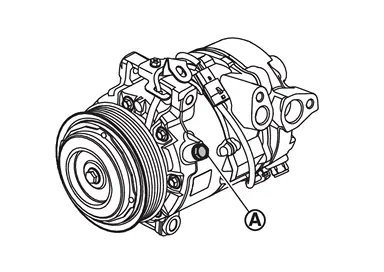
Drain lubricant from removed A/C compressor and measure lubricant amount.Remove drain bolt  , and then drain lubricant from drain port while rotating magnet clutch.
Drain lubricant from a new A/C compressor that is calculated according to the following conditions.
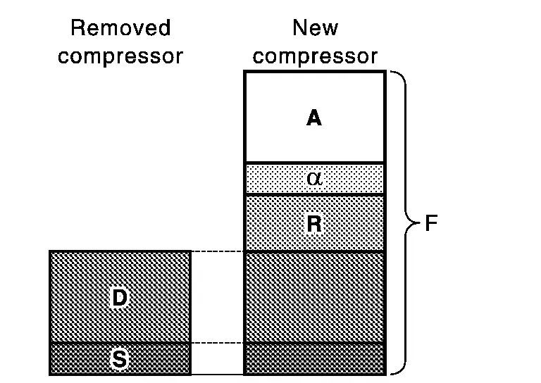
| Amount to be drained (A) [m (US fl oz, Imp fl oz)] = F − (D + S + R + α) |
|
| F | : Lubricant amount that a new A/C compressor contains [150 (5.1, 5.3)] |
| D | : Lubricant amount that is drained from removed A/C compressor |
| S | : Lubricant amount that remains inside of removed A/C compressor [20 (0.7, 0.7)] |
| R | : Lubricant amount to be added according to components that are removed except A/C compressor |
| α | : Lubricant amount that is recycled together with refrigerant during recycle operation |
CAUTION:
If lubricant amount that is drained from removed A/C compressor is less than 40 m (1.4 US fl oz, 1.4 Imp fl oz), perform calculation by setting “D� as 40 m (1.4 US fl oz, 1.4 Imp fl oz).
| Conditions |
Lubricant amount to be added to A/C system m (US fl oz, Imp fl oz) | |
|---|---|---|
| Replace evaporator | Front | 45 (1.5, 1.6) |
| Rear | 25 (0.8, 0.9) | |
| Replace condenser & liquid tank | 45 (1.5, 1.6) | |
Example: Lubricant amount to be drained from a new A/C compressor when replacing A/C compressor and condenser & liquid tank [m (US fl oz, Imp fl oz)] [D = 60 (2.0, 2.1), α = 5 (0.2, 0.2)]
150 (5.1, 5.3) − [60 (2.0, 2.1) + 20 (0.7, 0.7) + 45 (1.5, 1.6) + 5 (0.2, 0.2)] = 20 (0.7, 0.7)
Tighten drain bolt to the specified torque.
| Specified torque | : 30 N·m (3.1 kg-m, 22 ft-lb) |
Install A/C compressor and check the operation.
Other materials
Drive belts
Water pump
Alternator
Drive belt automatic tensioner
Crankshaft pulley
Air conditioning compressor
WARNING
Always ensure the ignition switch is OFF before inspecting or servicing the
drive belts on your Nissan Armada. Unexpected engine rotation can cause serious
injury.
1. Ca ...
A/t Fluid Cooler
Cleaning
Whenever an A/T is replaced, the A/T fluid cooler mounted in the radiator must be inspected and cleaned.Metal debris and friction material, if present, can become trapped in the A/T fluid cooler. This debris can contaminate the newly serviced A/T or, in severe cases, can block or restrict t ...
Replacement Operations
Precautions for Body Repair
WARNING:
Jacking up or lift up the vehicle may the vehicle height to go down which cause a personal injury and/or damage to the air suspension component parts. Refer to Precaution for when Jacking and Lifting Up the vehicle with Electronic Air Suspension System.
WAR ...