Precautions for Removing Battery Terminal
-
When disconnecting the 12V battery terminal, turn off the ACC power before disconnecting the 12V battery terminal, observing “How to disconnect 12V battery terminal� described below.
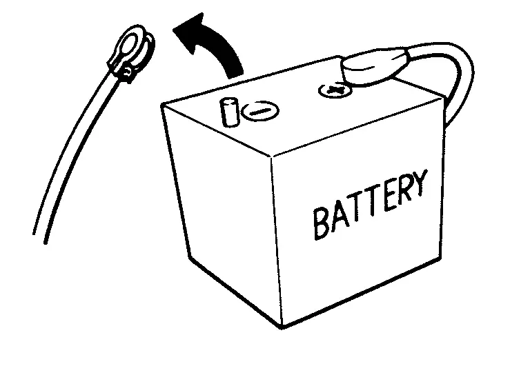
 NOTE:
NOTE:
Some ECUs operate for a certain fixed time even after ignition switch is turned OFF and ignition power supply is stopped. If the battery terminal is disconnected before ECU stops, accidental DTC detection or ECU data damage may occur.
-
For Nissan Armada vehicles with the 2-batteries, be sure to connect the main battery and the sub battery before turning ON the ignition switch.
NOTE:
If the ignition switch is turned ON with any one of the terminals of main battery and sub battery disconnected, then DTC may be detected.
-
After installing the 12V battery, always check "Self Diagnosis Result" of all ECUs and erase DTC.
NOTE:
The removal of 12V battery may cause a DTC detection error.
HOW TO DISCONNECT 12V BATTERY TERMINAL
Disconnect 12V battery terminal according to instruction described below.
-
Open the hood.
-
Turn ignition switch to the ON position.
-
Turn ignition switch to the OFF position with the driver side door opened.
-
Get out of the vehicle and close the driver side door.
-
Wait at least 3 minutes. For vehicle with the engine listed below, remove the battery terminal after a lapse of the specified time.
BR08DE : 4 minutes R9N engine : 12 minutes BR10DE : 12 minutes V9X engine : 4 minutes D4D engine : 20 minutes YD25DDTi : 2 minutes HR09DET : 12 minutes YS23DDT : 4 minutes HR10DDT : 12 minutes YS23DDTT : 4 minutes HR10DET : 12 minutes ZD30DDTi : 60 seconds HR13DDT : 12 minutes ZD30DDTT : 60 seconds HRA2DDT : 12 minutes K9K engine : 4 minutes M9R engine : 4 minutes R9M engine : 4 minutes CAUTION:
While waiting, never operate the vehicle such as locking, opening, and closing doors. Violation of this caution results in the activation of ACC power supply according to the Auto ACC function.
-
Remove 12V battery terminal.
CAUTION:
After installing 12V battery, always check self-diagnosis results of all ECUs and erase DTC.
Precaution for Supplemental Restraint System (SRS) "AIR BAG" and "SEAT BELT PRE-TENSIONER"
The Supplemental Restraint System such as “AIR BAG� and “SEAT BELT PRE-TENSIONER�, used along with a front seat belt, helps to reduce the risk or severity of injury to the driver and front passenger for certain types of collision.
Information necessary to service the system safely is included in the “SRS AIR BAG� and “SEAT BELT� of this Service Manual.
WARNING:
Always observe the following items for preventing accidental activation.
-
To avoid rendering the SRS inoperative, which could increase the risk of personal injury or death in the event of a collision that would result in air bag inflation, it is recommended that all maintenance and repair be performed by an authorized NISSAN/INFINITI dealer.
-
Improper repair, including incorrect removal and installation of the SRS, can lead to personal injury caused by unintentional activation of the system. For removal of Spiral Cable and Air Bag Module, see “SRS AIR BAG�.
-
Never use electrical test equipment on any circuit related to the SRS unless instructed to in this Service Manual. SRS wiring harnesses can be identified by yellow and/or orange harnesses or harness connectors.
PRECAUTIONS WHEN USING POWER TOOLS (AIR OR ELECTRIC) AND HAMMERS
WARNING:
Always observe the following items for preventing accidental activation.
-
When using air or electric power tools or hammers, always switch the ignition/power switch OFF, disconnect the 12V battery or batteries, and wait at least 3 minutes before performing any service.
Precaution for Brake System
WARNING:
Since dust covering the front and rear brakes has an affect on human body, the dust must be removed with a dust collector. Never splatter the dust with an air blow gun.
-
Brake fluid use refer to Fluids and Lubricants.
-
Never reuse drained brake fluid.
-
Never spill or splash brake fluid on painted surfaces. Brake fluid may seriously damage paint. Wipe it off immediately and wash with water if it gets on a painted surface.
-
Always confirm the specified tightening torque when installing the brake pipes.
-
After pressing the brake pedal more deeply or harder than normal driving, such as air bleeding, check each item of brake pedal. Adjust brake pedal if it is outside the standard value.
-
Never use mineral oils such as gasoline or light oil to clean. They may damage rubber parts and cause improper operation.
-
Always loosen the brake tube flare nut with a flare nut wrench.
-
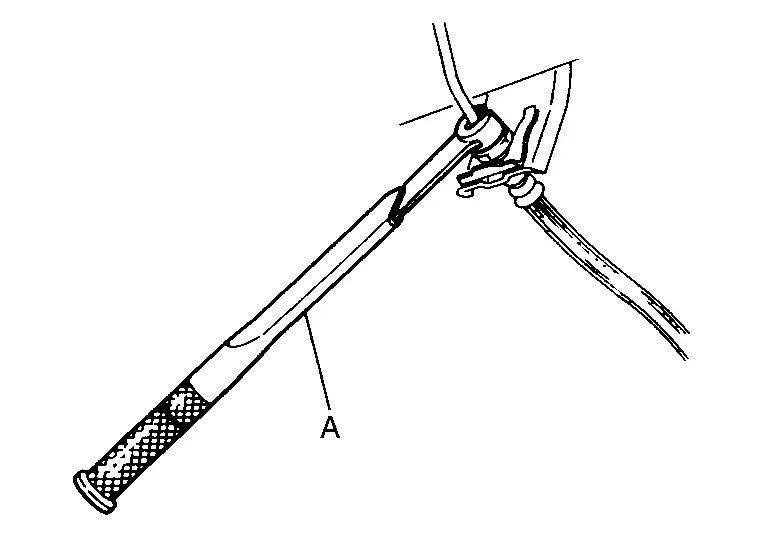
Tighten flare nut of brake tube to the specified torque using a flare nut torque wrench (A).
-
Ignition switch OFF and disconnect the ABS actuator and electric unit (control unit) harness connector or the 12V battery negative terminal before performing the work. Refer to Precautions for Removing Battery Terminal.
-
Check that no brake fluid leakage is present after replacing the parts.
Precaution for Brake Control System
-
Always perform a pre-driving check to drive the vehicle.
-
Always check speed and safety while driving the vehicle.
-
To operate CONSULT while driving, more than one person is required to be in the vehicle to avoid interference to driving and ensure safety.
-
Slight vibrations are felt on the brake pedal and the operation noises occur, when VDC function, TCS function, ABS function, EBD function, brake limited slip differential (BLSD) function, brake assist function, hill start assist function, advanced hill descent control function (4WD models), trailer sway control, or electric parking brake function operates. This is not a malfunction because it is caused by VDC function, TCS function, ABS function, EBD function, brake limited slip differential (BLSD) function, brake assist function, hill start assist function, advanced hill descent control function (4WD models), trailer sway control or electric parking brake function that is normally operated.
-
When starting engine or when starting vehicle just after starting engine, brake pedal may vibrate or motor operating noise may be heard from engine compartment. This is normal condition.
-
Brake stopping distance may become longer than models without ABS function depending on the road conditions, when ABS function is operated on slippery road like rough road, gravel road or snowy road.
-
When a malfunction is indicated, always collect information from the customer about conditions of occurrence, estimate cause, and perform operation. Check brake booster operation, brake fluid level, and brake fluid leakage, as well as electrical system.
-
The optimum performance is achieved by control for VDC function, TCS function, ABS function, EBD function, brake limited slip differential (BLSD) function, brake assist function, hill start assist function, advanced hill descent control function (4WD models), trailer sway control, and electric parking brake function when all of brakes, suspensions and tires installed on the vehicle are the specified size and parts. Brake performance and controllability may be negatively affected when other parts than the specified are installed.
-
Brake stopping distance may become longer and steering stability may be negatively affected, when tires in different size and combination or other parts than the specified are used.
-
When a radio (including wiring), antenna and antenna lead line are located near ABS actuator and electric unit (control unit), a malfunction or improper operation may occur for the control of VDC function, TCS function, ABS function, EBD function, brake limited slip differential (BLSD) function, brake assist function, hill start assist function, advanced hill descent control function (4WD models), trailer sway control, and electric parking brake function.
-
When the following items are replaced by other parts than genuine parts or modified, ABS warning lamp, brake warning lamp and VDC warning lamp may turn ON, and the control may not operate normally for VDC function, TCS function, ABS function, EBD function, brake limited slip differential (BLSD) function, brake assist function, hill start assist function, advanced hill descent control function (4WD models), trailer sway control, and electric parking brake function.
-
Suspension component parts (shock absorber, spring, bushing and others)
-
Tire and wheel (other than the specified size)
-
Brake component parts (brake pad, disc rotor, brake caliper and others)
-
Engine component parts (ECM, muffler and others)
-
Body reinforcement component parts (rollover bar, tower bar and others)
-
-
When suspension, tire and brake related parts are excessively worn or deteriorated and the vehicle is driven, ABS warning lamp, brake warning lamp and VDC warning lamp may turn ON, and the control may not operate normally for VDC function, TCS function, ABS function, EBD function, brake limited slip differential (BLSD) function, brake assist function, hill start assist function, advanced hill descent control function (4WD models), trailer sway control, and electric parking brake function.
-
ABS warning lamp, brake warning lamp and VDC warning lamp may turn ON, when only front wheel or rear wheel is rotated using a free roller. This is not a malfunction, because it is caused by wheel speed difference between wheel that is rotated and wheel that is not rotated. In this case, perform self-diagnosis, check self-diagnosis results, and erase memory.
-
When power supply voltage is not normal, ABS warning lamp, brake warning lamp and VDC warning lamp turn ON. ABS actuator and electric unit (control unit) stops control for VDC function, TCS function, ABS function, EBD function, brake limited slip differential (BLSD) function, brake assist function, hill start assist function, advanced hill descent control function (4WD models), trailer sway control, and electric parking brake function. Ordinary brake operates. After power supply returns to normal, ABS warning lamp, brake warning lamp and VDC warning lamp turn OFF. The control becomes operative for VDC function, TCS function, ABS function, EBD function, brake limited slip differential (BLSD) function, brake assist function, hill start assist function, advanced hill descent control function (4WD models), trailer sway control, and electric parking brake function.
-
Brake pedal vibrates and operation sound occurs during sudden acceleration and cornering, when VDC function, TCS function, brake limited slip differential (BLSD) function, brake assist function, hill start assist function, advanced hill descent control function (4WD models), trailer sway control, and electric parking brake function. This is not a malfunction because it is caused by VDC function, TCS function, brake limited slip differential (BLSD) function, brake assist function, hill start assist function, advanced hill descent control function (4WD models), trailer sway control, and electric parking brake function that is operated normally.
-
VDC warning lamp may turn ON and VDC function, TCS function, brake limited slip differential (BLSD) function, brake assist function, hill start assist function, advanced hill descent control function (4WD models), trailer sway control, and electric parking brake function may not normally operate, when driving on a special road the is extremely slanted (bank in a circuit course). This is not a malfunction if the status returns to normal for VDC function, TCS function, brake limited slip differential (BLSD) function, brake assist function, hill start assist function, advanced hill descent control function (4WD models), trailer sway control, and electric parking brake function after the engine is started again. In this case, perform self-diagnosis, check self-diagnosis results, and erase memory.
-
A malfunction in yaw rate/side/decel G sensor system may be detected when the vehicle sharply turns during a spin turn, acceleration turn or drift driving while VDC function and TCS function are OFF (VDC OFF indicator lamp is in ON status). This is not a malfunction if the status returns to normal for VDC function and TCS function after the engine is started again. In this case, perform self-diagnosis, check self-diagnosis results, and erase memory.
Precautions for Harness Repair
-
Solder the repaired area and wrap tape around the soldered area.
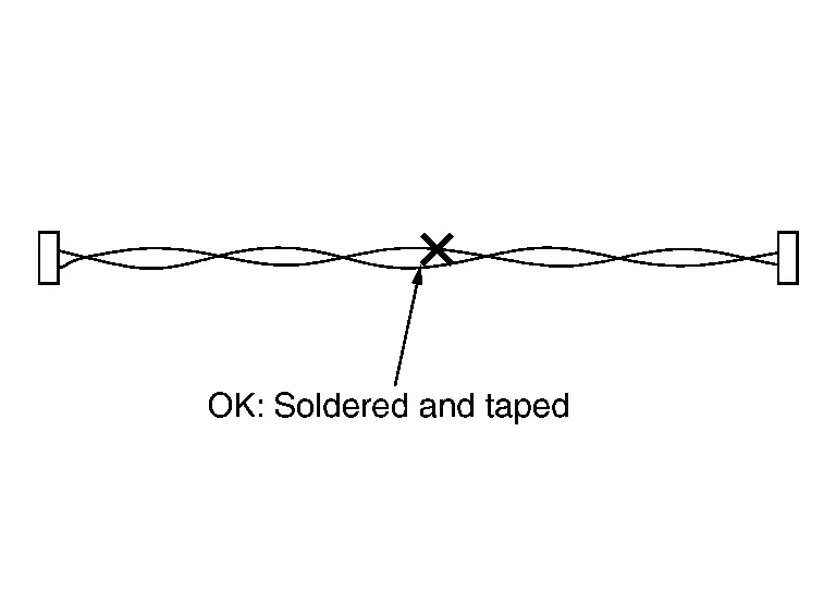 NOTE:
NOTE:
A fray of twisted lines must be within 110 mm (4.33 in).
-
Bypass connection is never allowed at the repaired area.
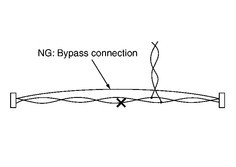 NOTE:
NOTE:
Bypass connection may cause CAN communication error. The spliced wire becomes separated and the characteristics of twisted line are lost.
-
Replace the applicable harness as an assembly if error is detected on the shield lines of CAN communication line.
Precaution for when Jacking and Lifting Up the Vehicle with Electronic Air Suspension System
WARNING:
-
When jacking up or lift up the vehicle, always turn OFF the electronic air suspension function with the vehicle unladen and normal height, since the suspension may accidentally move and it can lead to personal injury.
-
When removing the air suspension component parts, always follow the removing procedure since the vehicle height may accidentally drop and it can lead to personal injury.
CAUTION:
When jacking up or lift up the vehicle, always turn OFF the electronic air suspension function with the vehicle unladen and normal height to prevent damage to the air suspension component parts.
OPERATION PROCEDURE
Jacking up or lift up using the following steps.
-
Start engine.
-
Turn auto height mode control switch to ON, shift the shift position to N and set to normal height.
-
Turn OFF the electronic air suspension function. Refer to Operation.
-
Stop engine.
-
Jacking up or lift up.
Precaution for Electronic Air Suspension System
WARNING:
-
When removing the air suspension component parts, always follow the removing procedure since the vehicle height may accidentally drop and it can lead to personal injury.
CAUTION:
-
Never expand and contract the air spring of shock absorber.
-
Never expand and contract the air spring.
-
Never let foreign materials entered into parts.
-
Always check for the air leakage with soapy water after working.
-
Be sure to close the hood after working.
-
Turn ON the electronic air suspension function after working. Refer to Operation.
-
Air suspension component parts may be rusted if de-icer is put in excessively to prevent freezing because it cannot remove moisture in pneumatic circuit.
-
Replacing suspension component parts other than genuine parts may cause low performance of air suspension and calibration failure.
Other materials
Front, side and rear unique parts (NISMO models)
The Nissan Armada NISMO models are equipped with distinctive aerodynamic and
styling components that enhance both performance and visual appeal at the front,
sides, and rear of the vehicle.
Front spoiler
Side sill extensions
Rear bumper with the aerodynamic diffuser
CAUTION
...
Low-Pressure Flexible Hose
Removal and Installation
REMOVALCAUTION:
Perform lubricant return operation before each refrigeration system disassembly. However, if a large amount of refrigerant or lubricant leak is detected, never perform lubricant return operation. Refer to Perform Lubricant Return Operation.
When disconnec ...
Precautions
Precautions for Body Repair
WARNING:
Jacking up or lift up the vehicle may the vehicle height to go down which cause a personal injury and/or damage to the air suspension component parts. Refer to Precaution for when Jacking and Lifting Up the vehicle with Electronic Air Suspension System.
WAR ...