Precaution for Supplemental Restraint System (SRS) "AIR BAG" and "SEAT BELT PRE-TENSIONER"
The Supplemental Restraint System such as “AIR BAG� and “SEAT BELT PRE-TENSIONER�, used along with a front seat belt, helps to reduce the risk or severity of injury to the driver and front passenger for certain types of collision.
Information necessary to service the system safely is included in the “SRS AIR BAG� and “SEAT BELT� of this Service Manual.
WARNING:
Always observe the following items for preventing accidental activation.
-
To avoid rendering the SRS inoperative, which could increase the risk of personal injury or death in the event of a collision that would result in air bag inflation, it is recommended that all maintenance and repair be performed by an authorized NISSAN/INFINITI dealer.
-
Improper repair, including incorrect removal and installation of the SRS, can lead to personal injury caused by unintentional activation of the system. For removal of Spiral Cable and Air Bag Module, see “SRS AIR BAG�.
-
Never use electrical test equipment on any circuit related to the SRS unless instructed to in this Service Manual. SRS wiring harnesses can be identified by yellow and/or orange harnesses or harness connectors.
PRECAUTIONS WHEN USING POWER TOOLS (AIR OR ELECTRIC) AND HAMMERS
WARNING:
Always observe the following items for preventing accidental activation.
-
When using air or electric power tools or hammers, always switch the ignition/power switch OFF, disconnect the 12V battery or batteries, and wait at least 3 minutes before performing any service.
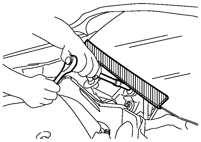
Precaution for Procedure without Cowl Top Cover
When performing the procedure after removing cowl top cover, cover the lower end of windshield with urethane, etc to prevent damage to windshield.
Precautions for Removing Battery Terminal
-
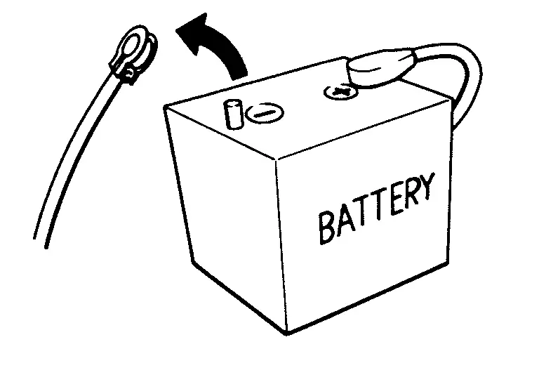
When disconnecting the 12V battery terminal, turn off the ACC power before disconnecting the 12V battery terminal, observing “How to disconnect 12V battery terminal� described below.
 NOTE:
NOTE:
Some ECUs operate for a certain fixed time even after ignition switch is turned OFF and ignition power supply is stopped. If the battery terminal is disconnected before ECU stops, accidental DTC detection or ECU data damage may occur.
-
For Nissan Armada vehicles with the 2-batteries, be sure to connect the main battery and the sub battery before turning ON the ignition switch.
NOTE:
If the ignition switch is turned ON with any one of the terminals of main battery and sub battery disconnected, then DTC may be detected.
-
After installing the 12V battery, always check "Self Diagnosis Result" of all ECUs and erase DTC.
NOTE:
The removal of 12V battery may cause a DTC detection error.
HOW TO DISCONNECT 12V BATTERY TERMINAL
Disconnect 12V battery terminal according to instruction described below.
-
Open the hood.
-
Turn ignition switch to the ON position.
-
Turn ignition switch to the OFF position with the driver side door opened.
-
Get out of the vehicle and close the driver side door.
-
Wait at least 3 minutes. For vehicle with the engine listed below, remove the battery terminal after a lapse of the specified time.
BR08DE : 4 minutes R9N engine : 12 minutes BR10DE : 12 minutes V9X engine : 4 minutes D4D engine : 20 minutes YD25DDTi : 2 minutes HR09DET : 12 minutes YS23DDT : 4 minutes HR10DDT : 12 minutes YS23DDTT : 4 minutes HR10DET : 12 minutes ZD30DDTi : 60 seconds HR13DDT : 12 minutes ZD30DDTT : 60 seconds HRA2DDT : 12 minutes K9K engine : 4 minutes M9R engine : 4 minutes R9M engine : 4 minutes CAUTION:
While waiting, never operate the vehicle such as locking, opening, and closing doors. Violation of this caution results in the activation of ACC power supply according to the Auto ACC function.
-
Remove 12V battery terminal.
CAUTION:
After installing 12V battery, always check self-diagnosis results of all ECUs and erase DTC.
Precaution for when Jacking and Lifting Up the Vehicle with Electronic Air Suspension System
WARNING:
-
When jacking up or lift up the vehicle, always turn OFF the electronic air suspension function with the vehicle unladen and normal height, since the suspension may accidentally move and it can lead to personal injury.
-
When removing the air suspension component parts, always follow the removing procedure since the vehicle height may accidentally drop and it can lead to personal injury.
CAUTION:
When jacking up or lift up the vehicle, always turn OFF the electronic air suspension function with the vehicle unladen and normal height to prevent damage to the air suspension component parts.
OPERATION PROCEDURE
Jacking up or lift up using the following steps.
-
Start engine.
-
Turn auto height mode control switch to ON, shift the shift position to N and set to normal height.
-
Turn OFF the electronic air suspension function. Refer to Operation.
-
Stop engine.
-
Jacking up or lift up.
Precaution for Electronic Air Suspension System
WARNING:
-
When removing the air suspension component parts, always follow the removing procedure since the vehicle height may accidentally drop and it can lead to personal injury.
CAUTION:
-
Never expand and contract the air spring of shock absorber.
-
Never expand and contract the air spring.
-
Never let foreign materials entered into parts.
-
Always check for the air leakage with soapy water after working.
-
Be sure to close the hood after working.
-
Turn ON the electronic air suspension function after working. Refer to Operation.
-
Air suspension component parts may be rusted if de-icer is put in excessively to prevent freezing because it cannot remove moisture in pneumatic circuit.
-
Replacing suspension component parts other than genuine parts may cause low performance of air suspension and calibration failure.
Precautions For Refrigerant System Service
GENERAL REFRIGERANT PRECAUTION
WARNING:
-
Never breathe A/C refrigerant and lubricant vapor or mist. Exposure may irritate eyes, nose and throat. Remove HFO-1234yf (R-1234yf) from the A/C system, using certified service equipment meeting requirements of SAE J2843 [HFO-1234yf (R-1234yf) Recovery/Recycling/Recharging Equipment for Flammable Refrigerants for Mobile Air Conditioning Systems] Ventilate work area before resuming service if accidental system discharge occurs. Additional health and safety information may be obtained from refrigerant and lubricant manufacturers.
-
Never release refrigerant into the air. Use approved recovery/recycling recharging equipment to capture the refrigerant each time an air conditioning system is discharged.
-
Wear always eye and hand protection (goggles and gloves) when working with any refrigerant or air conditioning system.
-
Never place the refrigerant containers and recovery/recycling equipment in a place where the temperature exceeds 40°C (104°F).
-
Never heat a refrigerant container with an open flame; Place the bottom of the container in a warm pail of water if container warming is required.
-
Never intentionally drop, puncture, or incinerate refrigerant containers.
-
Keep refrigerant away from open flames: poisonous gas is produced if refrigerant burns.
-
Refrigerant displaces oxygen, therefore be certain to work in well ventilated areas to prevent suffocation.
-
Never pressure test or leakage test HFO-1234yf (R-1234yf) service equipment and/or vehicle air conditioning systems with compressed air during repair. Some mixtures of air and HFO-1234yf (R-1234yf) have been shown to be combustible at elevated pressures. These mixtures, if ignited, may cause injury or property damage. Additional health and safety information may be obtained from refrigerant manufacturers.
WORKING WITH HFO-1234yf (R-1234YF)
CAUTION:
-
CFC-12 (R-12) or HFC-134a (R-134a) refrigerant and HFO-1234yf (R-1234yf) refrigerant are not compatible. A/C compressor malfunction is likely to occur if the refrigerants are mixed, refer to “CONTAMINATED REFRIGERANT� below. To determine the purity of HFO-1234yf (R-1234yf) in the vehicle and recovery tank, use Refrigerant recovery/recycling recharging equipment and Refrigerant Identifier.
-
Use only specified lubricant for the HFO-1234yf (R-1234yf) A/C system and HFO-1234yf (R-1234yf) components. If a compressor oil that does not meet the specifications is used, it will be worn and damaged due to poor lubrication, and the cooling and dehumidifying functions will be significantly reduced.
-
The specified HFO-1234yf (R-1234yf) lubricant rapidly absorbs moisture from the atmosphere. The following handling precautions must be observed:
-
Cap (seal) immediately the component to minimize the entry of moisture from the atmosphere when removing refrigerant components from a vehicle.
-
Never remove the caps (unseal) until just before connecting the components when installing refrigerant components to a vehicle. Connect all refrigerant loop components as quickly as possible to minimize the entry of moisture into system.
-
Use only the specified lubricant from a sealed container. Reseal immediately containers of lubricant. Lubricant becomes moisture saturated and should not be used without proper sealing.
-
Never allow lubricant to come in contact with styrene foam parts. Damage may result.
-
CONTAMINATED REFRIGERANT
Take appropriate steps shown below if a refrigerant other than pure HFO-1234yf (R-1234yf) is identified in a vehicle:
-
Explain to the customer that environmental regulations prohibit the release of contaminated refrigerant into the atmosphere.
-
Explain that recovery of the contaminated refrigerant could damage service equipment and refrigerant supply.
-
Suggest the customer return the vehicle to the location of previous service where the contamination may have occurred.
-
In case of repairing, recover the refrigerant using only dedicated equipment and containers. Never recover contaminated refrigerant into the existing service equipment. Contact a local refrigerant product retailer for available service if the facility does not have dedicated recovery equipment. This refrigerant must be disposed of in accordance with all federal and local regulations. In addition, replacement of all refrigerant system components on the vehicle is recommended.
-
The air conditioner warranty is void if the vehicle is within the warranty period. Please contact Nissan Customer Affairs for further assistance.
REFRIGERANT CONNECTION
WARNING:
Check that all refrigerant is discharged into the recycling equipment and the pressure in the system is less than atmospheric pressure. Then gradually loosen the discharge side hose fitting and remove it.
CAUTION:
Observe the following when replacing or cleaning refrigerant cycle components.
-
Store it in the same way at it is when mounted on the car when the A/C compressor is removed. Failure to do so will cause lubricant to enter the low-pressure chamber.
-
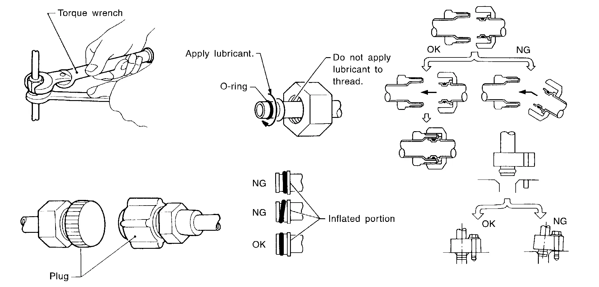
Use always a torque wrench and a back-up wrench when connecting tubes.
-
Plug immediately all openings to prevent entry of dust and moisture after disconnecting tubes.
-
Connect the pipes at the final stage of the operation when installing an air conditioner in the vehicle. Never remove the seal caps of pipes and other components until just before required for connection.
-
Allow components stored in cool areas to warm to working area temperature before removing seal caps. This prevents condensation from forming inside A/C components.
-
Remove thoroughly moisture from the refrigeration system before charging the refrigerant.
-
Replace always used O-rings.
-
Apply lubricant to circle of the O-rings shown in illustration when connecting tube. Be careful not to apply lubricant to threaded portion.
-
O-ring must be closely attached to the groove portion of tube.
-
Be careful not to damage O-ring and tube when replacing the O-ring.
-
Connect tube until a click can be heard. Then tighten the nut or bolt by hand. Check that the O-ring is installed to tube correctly.
-
Perform leakage test and make sure that there is no leakage from connections after connecting line. Disconnect that line and replace the O-ring when the refrigerant leaking point is found. Then tighten connections of seal seat to the specified torque.
A/C COMPRESSOR
CAUTION:
-
Plug all openings to prevent moisture and foreign matter from entering.
-
Store it in the same way at it is when mounted on the car when the A/C compressor is removed.
-
Follow “MAINTENANCE OF LUBRICANT LEVEL� exactly when replacing or repairing A/C compressor. Refer to Description.
-
Keep friction surfaces between clutch and pulley clean. Wipe it off by using a clean waste cloth moistened with thinner if the surface is contaminated with lubricant.
-
Turn the A/C compressor shaft by hand more than five turns in both directions after A/C compressor service operation. This distributes equally lubricant inside the A/C compressor. Let the engine idle and operate the A/C compressor for one hour after the A/C compressor is installed.
Service Equipment
RECOVERY/RECYCLING RECHARGING EQUIPMENT
Be certain to follow the manufacturer’s instructions for machine operation and machine maintenance. Never introduce any refrigerant other than that specified into the machine.
ELECTRICAL LEAK DETECTOR
Be certain to follow the manufacturer’s instructions for tester operation and tester maintenance.
VACUUM PUMP
The lubricant contained inside the vacuum pump is not compatible with the specified lubricant for HFO-1234yf (R-1234yf) A/C systems. The vent side of the vacuum pump is exposed to atmospheric pressure. So the vacuum pump lubricant may migrate out of the pump into the service hose. This is possible when the pump is switched OFF after evacuation (vacuuming) and hose is connected to it.
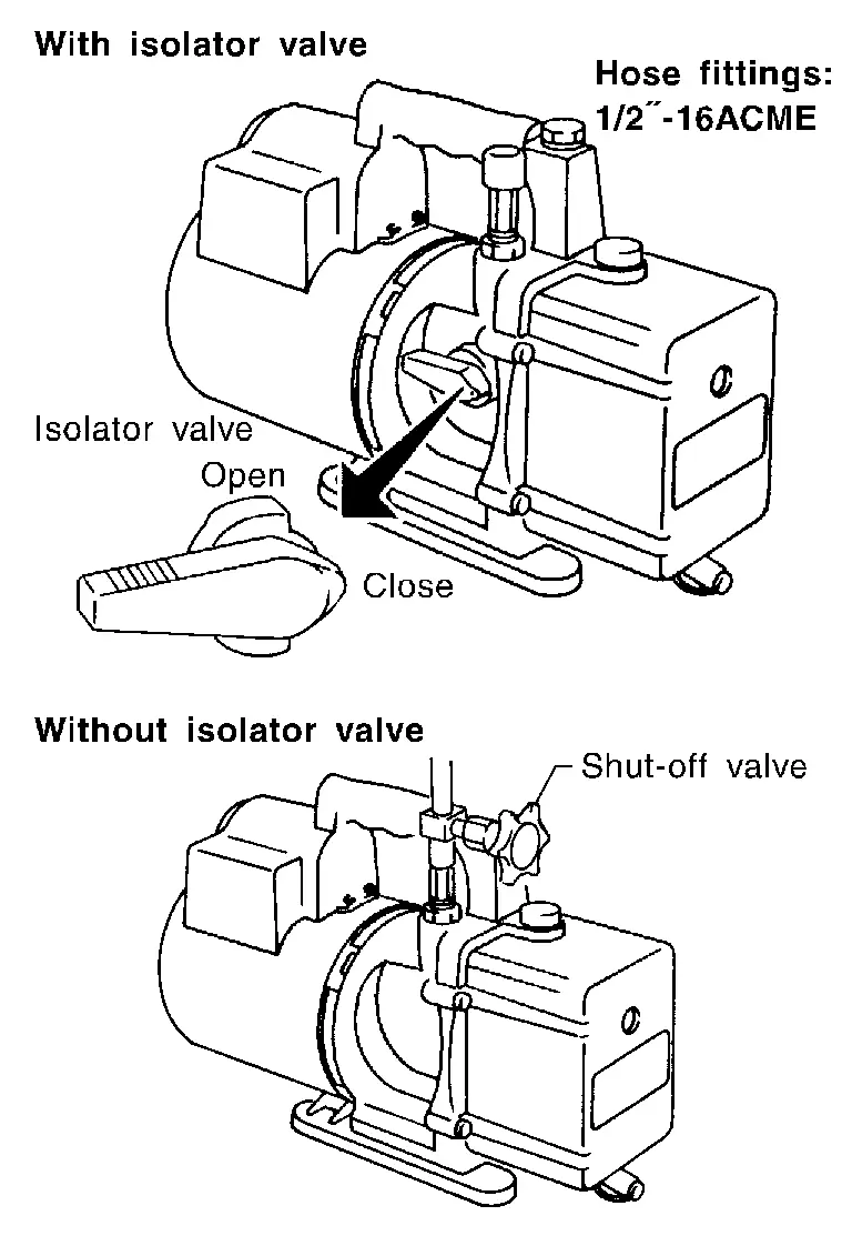
To prevent this migration, use a manual valve placed near the hose-to-pump connection, as per the following.
-
Vacuum pumps usually have a manual isolator valve as part of the pump. Close this valve to isolate the service hose from the pump.
-
Use a hose equipped with a manual shut-off valve near the pump end for pumps without an isolator. Close the valve to isolate the hose from the pump.
-
Disconnect the hose from the pump if the hose has an automatic shut-off valve. As long as the hose is connected, the valve is open and lubricating oil may migrate.
Some one-way valves open when vacuum is applied and close under no vacuum condition. Such valves may restrict the pump’s ability to pull a deep vacuum and are not recommended.
MANIFOLD GAUGE SET
Be certain that the gauge face indicates HFO-1234yf or R-1234yf. Be sure the gauge set has threaded connections for HFO-1234yf (R-1234yf) service hoses. Confirm the set has been used only with refrigerant HFO-1234yf (R-1234yf) and specified lubricants.
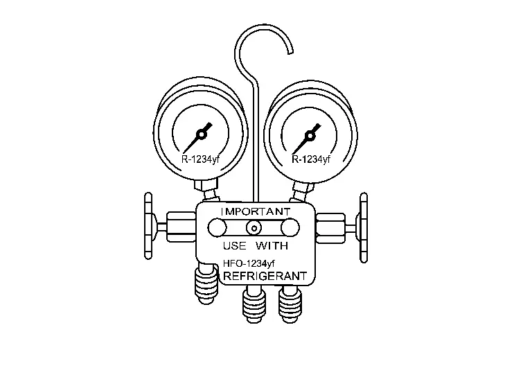
SERVICE HOSES
All hoses must equip positive shut-off devices (either manual or automatic) near the end of the hoses opposite to the manifold gauge.

SERVICE COUPLERS
Never attempt to connect HFO-1234yf (R-1234yf) service couplers to the CFC-12 (R-12) and HFC-134a (R-134a) A/C system. The HFO-1234yf (R-1234yf) couplers do not properly connect to the CFC-12 (R-12) and HFC-134a (R-134a) system. However, if an improper connection is attempted, discharging and contamination may occur.
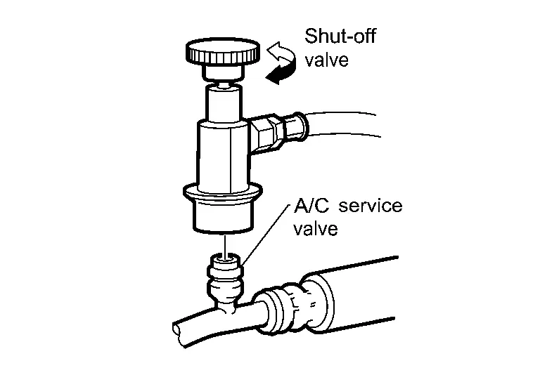
| Shut-off valve rotation | A/C service valve |
|---|---|
| Clockwise | Open |
| Counterclockwise | Close |
REFRIGERANT WEIGHT SCALE
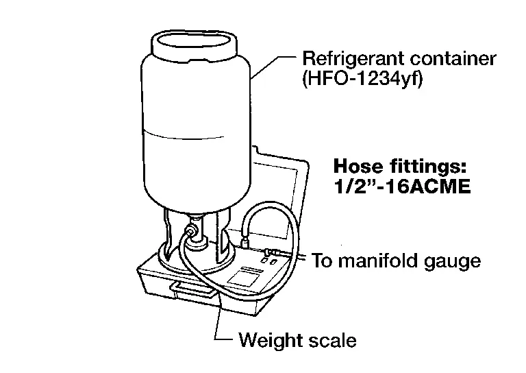
Verify that no refrigerant other than HFO-1234yf (R-1234yf) and specified lubricants have been used with the scale. The hose fitting must be 1/2″-16 ACME if the scale controls refrigerant flow electronically.
CHARGING CYLINDER
Using a charging cylinder is not recommended. Refrigerant may be vented into air from cylinder’s top valve when filling the cylinder with refrigerant. Also, the accuracy of the cylinder is generally less than that of an electronic scale or of quality recycle/recharge equipment.
Other materials
Rear
Exploded View
Brake tube
Brake hose
Lock plate
Union bolt
Copper washer
To front brake tube. Refer to Exploded View.
: vehicle front
: N·m (kg-m, ft-lb)
: N·m (kg-m, in- ...
Automatic Back Door Control Unit
Removal and Installation
REMOVALRemove luggage side lower finisher LH. Refer to Removal and Installation.
Disconnect automatic back door control unit harness connector.
Remove automatic back door control unit mounting nuts , and then remove automatic back door control unit .
INSTALLATIONInstall in ...
Shipping Mode Cancel Operation
Work Procedure
SHIPPING MODE CANCEL OPERATION
Ignition switch OFF.
Push in (switch on) the extended storage fuse switch. Refer to How To Check.
Ignition switch ON.
Ignition switch OFF and wait at least 2 seconds.
>>
GO TO 2.
SHIPPING MODE CANCEL CHECK
Ignition switch ON.
Check ...