Precaution for Supplemental Restraint System (SRS) "AIR BAG" and "SEAT BELT PRE-TENSIONER"
The Supplemental Restraint System such as “AIR BAG� and “SEAT BELT PRE-TENSIONER�, used along with a front seat belt, helps to reduce the risk or severity of injury to the driver and front passenger for certain types of collision.
Information necessary to service the system safely is included in the “SRS AIR BAG� and “SEAT BELT� of this Service Manual.
WARNING:
Always observe the following items for preventing accidental activation.
-
To avoid rendering the SRS inoperative, which could increase the risk of personal injury or death in the event of a collision that would result in air bag inflation, it is recommended that all maintenance and repair be performed by an authorized NISSAN/INFINITI dealer.
-
Improper repair, including incorrect removal and installation of the SRS, can lead to personal injury caused by unintentional activation of the system. For removal of Spiral Cable and Air Bag Module, see “SRS AIR BAG�.
-
Never use electrical test equipment on any circuit related to the SRS unless instructed to in this Service Manual. SRS wiring harnesses can be identified by yellow and/or orange harnesses or harness connectors.
PRECAUTIONS WHEN USING POWER TOOLS (AIR OR ELECTRIC) AND HAMMERS
WARNING:
Always observe the following items for preventing accidental activation.
-
When using air or electric power tools or hammers, always switch the ignition/power switch OFF, disconnect the 12V battery or batteries, and wait at least 3 minutes before performing any service.
Precaution Necessary for Steering Wheel Rotation After Battery Disconnect
CAUTION:
Comply with the following cautions to prevent any error and malfunction.
-
Before removing and installing any control units, first turn the ignition power source and accessory power source to the OFF, then disconnect both battery cables.
-
After finishing work, confirm that all control unit connectors are connected properly, then re-connect both battery cables.
-
Always use CONSULT to perform self-diagnosis as a part of each function inspection after finishing work. If a DTC is detected, perform trouble diagnosis according to self-diagnosis results.
For vehicle with steering lock unit, if the battery is disconnected or discharged, the steering wheel will lock and cannot be turned.
If turning the steering wheel is required with the battery disconnected or discharged, follow the operation procedure below before starting the repair operation.
OPERATION PROCEDURE
-
Connect both battery cables.
 NOTE:
NOTE:
Supply power using jumper cables if battery is discharged.
-
Open driver door.
-
Turn the ignition switch to the ON position.
(At this time, the steering lock will be released.)
-
Turn the ignition switch to OFF position with driver door open.
-
Wait for 3 minutes or longer with driver door open.
NOTE:
-
Do not close driver door because the steering wheel locks when driver door is closed.
-
The auto acc function is adapted to this vehicle. For this reason, even when the ignition switch is turned to OFF position, the accessory power source does not turned OFF and continues to be supplied for a certain amount of time.
-
-
Disconnect both battery cables. The steering lock will remain released with both battery cables disconnected and the steering wheel can be turned.
-
Perform the necessary repair operation.
-
When the repair work is completed, re-connect both battery cables. With the brake pedal released, turn the ignition switch from OFF position to ON position, then to LOCK position. (The steering wheel will lock when the ignition switch is turned to LOCK position.)
-
Perform self-diagnosis check of all control units using CONSULT.
Precautions for Removing Battery Terminal
-
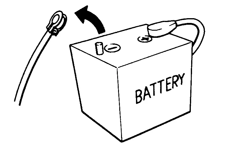
When disconnecting the 12V battery terminal, turn off the ACC power before disconnecting the 12V battery terminal, observing “How to disconnect 12V battery terminal� described below.
 NOTE:
NOTE:
Some ECUs operate for a certain fixed time even after ignition switch is turned OFF and ignition power supply is stopped. If the battery terminal is disconnected before ECU stops, accidental DTC detection or ECU data damage may occur.
-
For Nissan Armada vehicles with the 2-batteries, be sure to connect the main battery and the sub battery before turning ON the ignition switch.
NOTE:
If the ignition switch is turned ON with any one of the terminals of main battery and sub battery disconnected, then DTC may be detected.
-
After installing the 12V battery, always check "Self Diagnosis Result" of all ECUs and erase DTC.
NOTE:
The removal of 12V battery may cause a DTC detection error.
HOW TO DISCONNECT 12V BATTERY TERMINAL
Disconnect 12V battery terminal according to instruction described below.
-
Open the hood.
-
Turn ignition switch to the ON position.
-
Turn ignition switch to the OFF position with the driver side door opened.
-
Get out of the vehicle and close the driver side door.
-
Wait at least 3 minutes. For vehicle with the engine listed below, remove the battery terminal after a lapse of the specified time.
BR08DE : 4 minutes R9N engine : 12 minutes BR10DE : 12 minutes V9X engine : 4 minutes D4D engine : 20 minutes YD25DDTi : 2 minutes HR09DET : 12 minutes YS23DDT : 4 minutes HR10DDT : 12 minutes YS23DDTT : 4 minutes HR10DET : 12 minutes ZD30DDTi : 60 seconds HR13DDT : 12 minutes ZD30DDTT : 60 seconds HRA2DDT : 12 minutes K9K engine : 4 minutes M9R engine : 4 minutes R9M engine : 4 minutes CAUTION:
While waiting, never operate the vehicle such as locking, opening, and closing doors. Violation of this caution results in the activation of ACC power supply according to the Auto ACC function.
-
Remove 12V battery terminal.
CAUTION:
After installing 12V battery, always check self-diagnosis results of all ECUs and erase DTC.
Precautions As to Battery Designed for Stop/Start System
-
Vehicles equipped with the stop/start system use a special battery designed for the stop/start system. This battery has upgrades in charge-discharge performance and lifetime.
-
It is mandatory to always use a battery designed for the stop/start system. Failure to do this causes early deterioration or system malfunction.
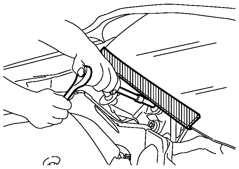
Precaution for Procedure without Cowl Top Cover
When performing the procedure after removing cowl top cover, cover the lower end of windshield with urethane, etc to prevent damage to windshield.
Precaution for Shift By Wire
CAUTION:
To avoid the risk of minor injury or property damage:
If the 12-volt battery has low or no voltage, the transmission cannot be shifted. Replace the battery or repair the damaged power supply system. If towing the vehicle, follow the tow procedure. Refer to Tow Truck Towing.
Precaution for when Jacking and Lifting Up the Vehicle with Electronic Air Suspension System
WARNING:
-
When jacking up or lift up the vehicle, always turn OFF the electronic air suspension function with the vehicle unladen and normal height, since the suspension may accidentally move and it can lead to personal injury.
-
When removing the air suspension component parts, always follow the removing procedure since the vehicle height may accidentally drop and it can lead to personal injury.
CAUTION:
When jacking up or lift up the vehicle, always turn OFF the electronic air suspension function with the vehicle unladen and normal height to prevent damage to the air suspension component parts.
OPERATION PROCEDURE
Jacking up or lift up using the following steps.
-
Start engine.
-
Turn auto height mode control switch to ON, shift the shift position to N and set to normal height.
-
Turn OFF the electronic air suspension function. Refer to Operation.
-
Stop engine.
-
Jacking up or lift up.
Other materials
Accelerator Pedal Released Position Learning
Description
Accelerator Pedal Released Position Learning is a function of ECM to learn the fully released position of the accelerator pedal by monitoring the accelerator pedal position sensor output signal. It must be performed each time the harness connector of the accelerator pedal position sensor ...
Diagnosis and Repair Work Flow
Work Flow
OVERALL SEQUENCEDETAILED FLOWGET INFORMATION FOR SYMPTOM
Get detailed information from the customer about the symptom (the condition and the environment when the incident/malfunction occurs).
Check operation condition of the function that is malfunctioning.
>>
GO TO 2.
CHECK ...
Hood Lock
Exploded View
Hood lock assembly
Hood lock control cable assembly
Hood lock control handle
: Clip
: Pawl
: N·m (kg-m, in-lb)
: Body grease
Hood Lock Assembly
Removal and Installation
REMOVALRemove front grille upper. Refer to Removal and Installation (OFF ROAD MODELS) or ...