Exploded View
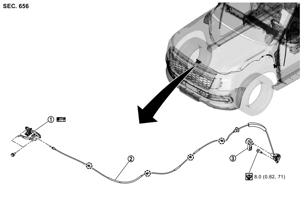
 |
Hood lock assembly |  |
Hood lock control cable assembly |  |
Hood lock control handle |
 |
: Clip | ||||
 |
: Pawl | ||||
 |
: N·m (kg-m, in-lb) | ||||
 |
: Body grease | ||||
Hood Lock Assembly
Removal and Installation
REMOVAL
Remove front grille upper. Refer to Removal and Installation (OFF ROAD MODELS) or Removal and Installation (CITY MODELS).
Disconnect hood lock switch harness connector (if equipped).
Remove hood lock assembly mounting bolts, and then remove hood lock assembly.
CAUTION:
Never bend hood lock control cable assembly strongly.
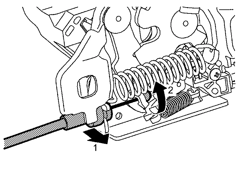
Disconnect hood lock control cable assembly from hood lock according to the numerical order 1→2 indicated by arrows as shown in figure.
INSTALLATION
Note the following items, and then install in the reverse order of removal.
CAUTION:
-
Check that hood lock control cable assembly is properly engaged with hood lock assembly.
-
When installation, perform hood fitting adjustment. Refer to Adjustment.
-
After installation, perform hood lock control inspection. Refer to Inspection.
Inspection
 NOTE:
NOTE:
If the hood lock control cable assembly is bent or deformed, replace it.
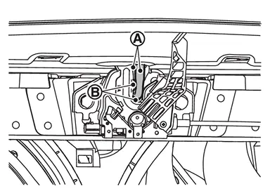
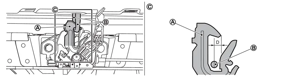
Check that secondary latch is securely engaged with bracket from dead load of hood assembly.
Check that primary latch  is securely engaged with hood striker
  when hood assembly is closed [freefall from approximately 200 mm (7.87 in) height].
CAUTION:
Never free-fall hood assembly from a height of 300 mm (11.81 in) or more.
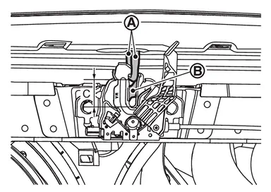
While operating the hood lock control handle carefully, check that the front end of the hood is lifted by approximately 20 mm (0.79 in) (C). Also, check that the hood lock control handle returns to the original position.
|
Hood striker | |
Primary latch |
Check that operating force of hood lock control handle shall be less than 49 N (5.0 kg, 11.0 lb).
Check pitch that secondary latch is properly engaged with hood striker [8.1 mm (0.319 in) MIN] (D).
Install so that static closing force of hood is 490 N (50.0 kg, 110.0 lb) or Less.
Check the hood lock assembly lubrication condition. If necessary, apply body grease to hood lock assembly.
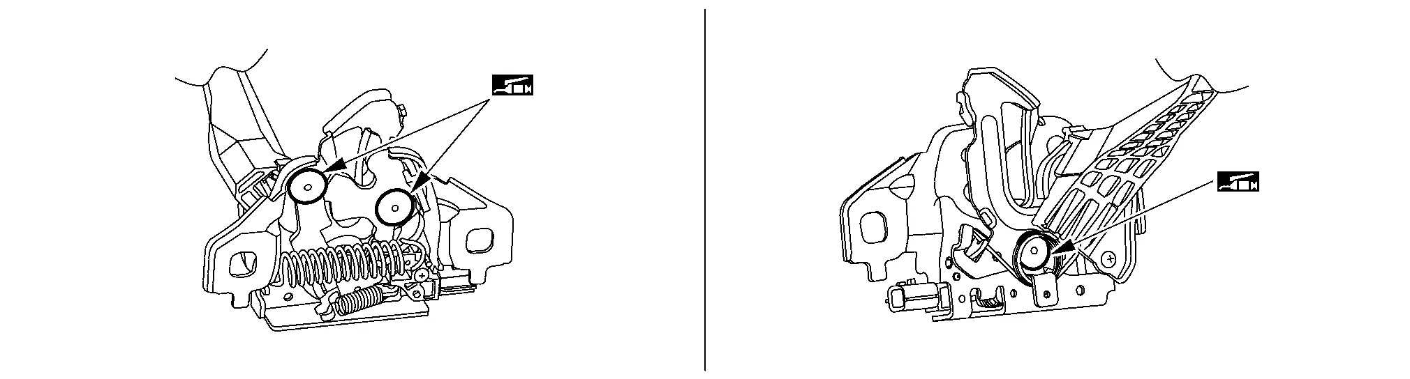
|
: Body grease |
Hood Lock Control Handle
Removal and Installation
REMOVAL
Disengage hood lock control handle fixing pawl, and then remove hood lock control handle.
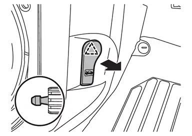
|
: Pawl |
INSTALLATION
Note the following items, and then install in the reverse order of removal.
CAUTION:
-
After installation, perform hood lock control inspection. Refer to Inspection.
-
After installation, check hood open/close operation.
Hood Lock Control Cable Assembly
Removal and Installation
REMOVAL
Disconnect hood lock control cable assembly from hood lock assembly. Refer to Removal and Installation.
Disengage hood lock control cable assembly fixing clips.
Remove hood lock control handle. Refer to Removal and Installation.
Remove dash side finisher LH. Refer to Removal and Installation.
Remove hood lock control cable assembly mounting bolt.
Remove grommet of the lower dash, and pull the hood lock control cable assembly toward inside vehicle.
CAUTION:
-
While pulling, never damage (peeling) the outside of hood lock control cable assembly.
-
Pull out the hood lock control cable assembly while turning over the insulator around the grommet part of hood lock control cable assembly.
INSTALLATION
Note the following items, and then install in the reverse order of removal.
CAUTION:
-
Never bend cable too much, keeping the radius 100 mm (3.94 in) or more.
-
Install grommet in the panel hole surely.
-
Check that cable is not offset from the positioning grommet, and apply the sealant to the grommet
properly.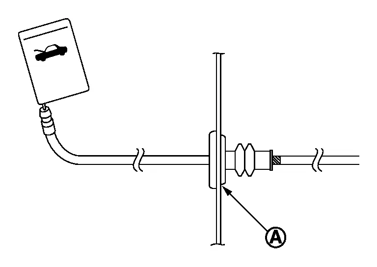
-
After installation, perform hood lock control inspection. Refer to Inspection.
Other materials
Additional Service When Replacing Electrical Brake Control Unit
Work Procedure
DescriptionWhen replacing the electrical brake control unit, the procedures of AFTER REPLACEMENT must be performed.CAUTION:
If the electrical brake control unit is undamaged, do not decide to replace it based on DTC detected in the past.AFTER REPLACEMENTAfter replacing the electrical ...
Push-Button Ignition Switch
Removal and Installation
REMOVALRemove instrument pad B. Refer to Removal and Installation.
Disengage the fixing pawls using a remover tool (A) and then remove push-button ignition switch from instrument pad B.
: Pawl
INSTALLATIONInstall in the reverse order of removal. ...
Additional Service When Replacing Chassis Control Module
Description
Vehicle specification needs to be written with CONSULT because it is not written after replacing the chassis control module. For details the operation, refer to “CONSULT Operation Manual�.
Work Procedure [After Replacing Chassis Control Module]
WRITING VEHICLE SPECIFICATION
With CONS ...