PRECAUTIONS FOR SUPPLEMENTAL RESTRAINT SYSTEM (SRS) AIR BAG AND SEAT BELT PRE-TENSIONER : Precautions
The Supplemental Restraint System such as “AIR BAG� and “SEAT BELT PRE-TENSIONER�, used along with a front seat belt, helps to reduce the risk or severity of injury to the driver and front passenger for certain types of collision.
Information necessary to service the system safely is included in the “SRS AIR BAG� and “SEAT BELT� of this Service Manual.
WARNING:
Always observe the following items for preventing accidental activation.
-
To avoid rendering the SRS inoperative, which could increase the risk of personal injury or death in the event of a collision that would result in air bag inflation, it is recommended that all maintenance and repair be performed by an authorized NISSAN/INFINITI dealer.
-
Improper repair, including incorrect removal and installation of the SRS, can lead to personal injury caused by unintentional activation of the system. For removal of Spiral Cable and Air Bag Module, see “SRS AIR BAG�.
-
Never use electrical test equipment on any circuit related to the SRS unless instructed to in this Service Manual. SRS wiring harnesses can be identified by yellow and/or orange harnesses or harness connectors.
PRECAUTIONS WHEN USING POWER TOOLS (AIR OR ELECTRIC) AND HAMMERS
WARNING:
Always observe the following items for preventing accidental activation.
-
When using air or electric power tools or hammers, always switch the ignition/power switch OFF, disconnect the 12V battery or batteries, and wait at least 3 minutes before performing any service.
PRECAUTIONS FOR REMOVING BATTERY TERMINAL : Precautions
When disconnecting the battery terminal, pay attention to the following.
-
Always use a 12V battery as power source.
-
Never disconnect battery terminal while engine is running.
-
When removing the 12V battery terminal, turn OFF the ignition switch and wait at least 30 seconds.
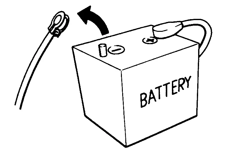
-
For Nissan Armada vehicles with the engine listed below, remove the battery terminal after a lapse of the specified time:
BR08DE : 4 minutes R9M engine : 4 minutes BR10DE : 12 minutes R9N engine : 12 minutes D4D engine : 20 minutes V9X engine : 4 minutes HR09DET : 12 minutes YD25DDTi : 2 minutes HR10DDT : 12 minutes YS23DDT : 4 minutes HR10DET : 12 minutes YS23DDTT : 4 minutes HR13DDT : 12 minutes ZD30DDTi : 60 seconds HRA0DET : 12 minutes ZD30DDTT : 60 seconds HRA2DDT : 12 minutes K9K engine : 4 minutes M9R engine : 4 minutes  NOTE:
NOTE:
ECU may be active for several tens of seconds after the ignition switch is turned OFF. If the battery terminal is removed before ECU stops, then a DTC detection error or ECU data corruption may occur.
-
After high-load driving, if the vehicle is equipped with the V9X engine, turn the ignition switch OFF and wait for at least 15 minutes to remove the battery terminal.
NOTE:
-
Turbocharger cooling pump may operate in a few minutes after the ignition switch is turned OFF.
-
Example of high-load driving
-
Driving for 30 minutes or more at 140 km/h (86 MPH) or more.
-
Driving for 30 minutes or more on a steep slope.
-
-
-
For Nissan Armada vehicles with the 2-batteries, be sure to connect the main battery and the sub battery before turning ON the ignition switch.
NOTE:
If the ignition switch is turned ON with any one of the terminals of main battery and sub battery disconnected, then DTC may be detected.
-
After installing the 12V battery, always check "Self Diagnosis Result" of all ECUs and erase DTC.
NOTE:
The removal of 12V battery may cause a DTC detection error.
Other materials
Exterior rear
Example
The rear exterior section of the Nissan Armada includes advanced safety sensors,
lighting systems, and cargo access features that enhance usability and safety during
reversing, towing, and everyday driving scenarios.
Fuel-filler door
Fuel information
Antenna**
Re ...
Shift Position
Inspection
CHECK SHIFT BUTTON OPERATION
When pressing each shift button of electric shift selector, check that each button is not twisted, stuck, or does not make noise and can be operated smoothly.
After pressing each shift button, check that all buttons return to original positions without sti ...
Selective Unlock Function Does Not Operate
Diagnosis Procedure
CHECK “SELECTIVE UNLOCK� SETTING IN COMBINATION METER
Check “selective unlock� setting is ON.
Is the inspection result normal?
YES>>
GO TO 2.
NO>>
Set “On� in combination meter.
REPLACE INTELLIGENT KEY UNIT
Replace Intelligent Key unit. Refer to Remova ...