Exploded View
REMOVAL
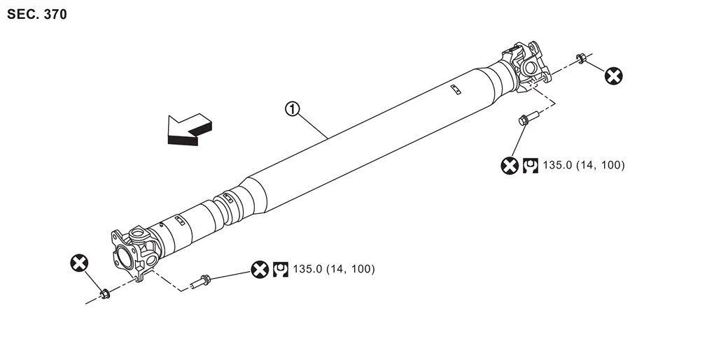
 |
Propeller shaft assembly |
| : vehicle front | |||||
 : N·m (kg-m, ft-lb) : N·m (kg-m, ft-lb) |
|||||
 : Always replace after every disassembly. : Always replace after every disassembly. |
DISASSEMBLY
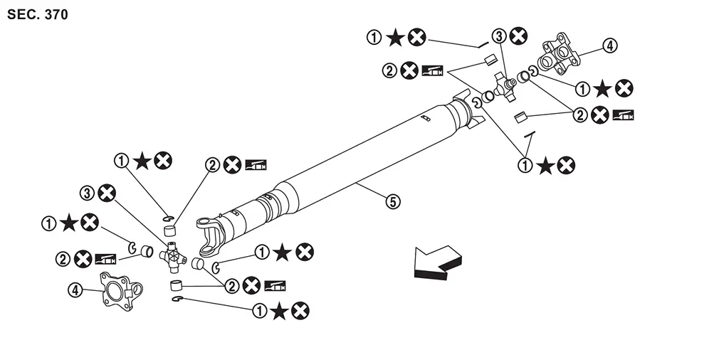
|
Snap ring |  |
Journal bearing |  |
Journal |
 |
Flange yoke |  |
Propeller shaft tube |
| : vehicle front | |||||
| : Always replace after every disassembly. |
|||||
 : Select with proper thickness. : Select with proper thickness. |
|||||
 : Apply multi-purpose grease. : Apply multi-purpose grease. |
 NOTE:
NOTE:
Replace , and as a set.
Removal and Installation
WARNING:
-
Jacking up or lift up the vehicle may the vehicle height to go down which cause a personal injury and/or damage to the air suspension component parts. Refer to Precaution for when Jacking and Lifting Up the vehicle with Electronic Air Suspension System.
REMOVAL
Shift the transmission to the neutral position, and then release the parking brake.
Put matching mark  on rear propeller shaft flange yoke and final drive companion flange.
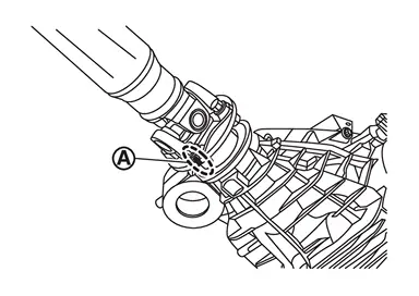
CAUTION:
For matching mark, use paint. Never damage propeller shaft flange and final drive companion flange.
Put matching mark on rear propeller shaft flange yoke and transfer companion flange.
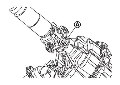
CAUTION:
For matching mark, use paint. Never damage propeller shaft flange and transfer companion flange.
Remove propeller shaft assembly fixing bolts and nuts.
Remove propeller shaft assembly from vehicle.
Perform inspection after removal. Refer to Inspection.
INSTALLATION
Note the following, and install in the reverse order of removal.
-
For non-reusable parts, refer to Exploded View.
-
For each tightening torque, refer to Exploded View.
-
Align matching marks
to install propeller shaft flange yoke and transfer companion flange. -
Align matching marks
to install propeller shaft flange yoke and final drive companion flange. -
If propeller shaft assembly or final drive assembly has been replaced, connect them as follows:
-
Install propeller shaft
while aligning matching mark of propeller shaft with matching mark  of final drive on the joint as close as possible.
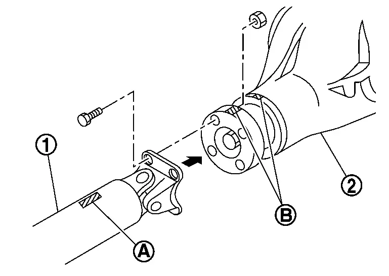 NOTE:
NOTE:
Matching mark
is has been painted in either position.
-
-
Perform inspection after installation. Refer to Inspection.
Disassembly and Assembly
DISASSEMBLY
Put a matching mark between propeller shaft and flange yoke as shown.
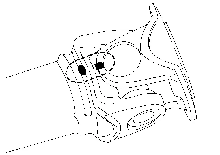
CAUTION:
For matching mark, use paint. Never damage the surface.
Remove snap rings .
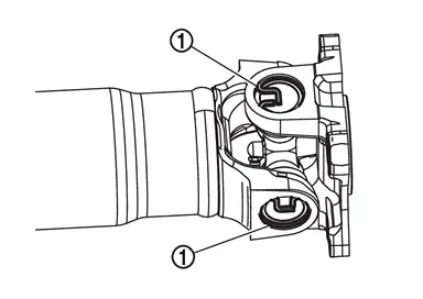
Lightly tap bottom of yoke using a copper hammer and remove journal bearing.
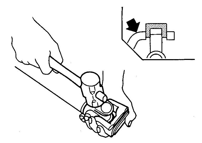
CAUTION:
Never damage the yoke.
ASSEMBLY
Install journal bearing to journal.
CAUTION:
-
Never reuse journal and journal bearing.
-
Always replace journal, journal bearing, and snap rings as a set.
-
Apply multi-purpose grease to journal bearing.
-
Install bearing
using a vise.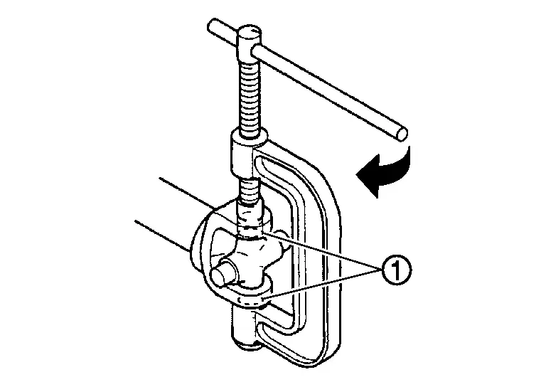
CAUTION:
Never damage bearing or flange yoke.
Measure journal axial play. If necessary, select the appropriate snap ring.While pushing to 98 N·m (10 kg-m, 72 ft-lb), check the clearance between snap ring and needle bearing .
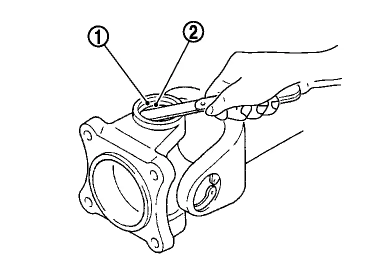
| Journal axial play | : Refer to Journal. |
CAUTION:
-
Never reuse snap ring.
-
Select snap rings with a difference in thickness at both sides within 0.02 mm (0.0008 in). For selecting snap ring, refer to the latest parts information.
Install snap rings .
Check that the journal moves smoothly and is below the joint flex torque specification.
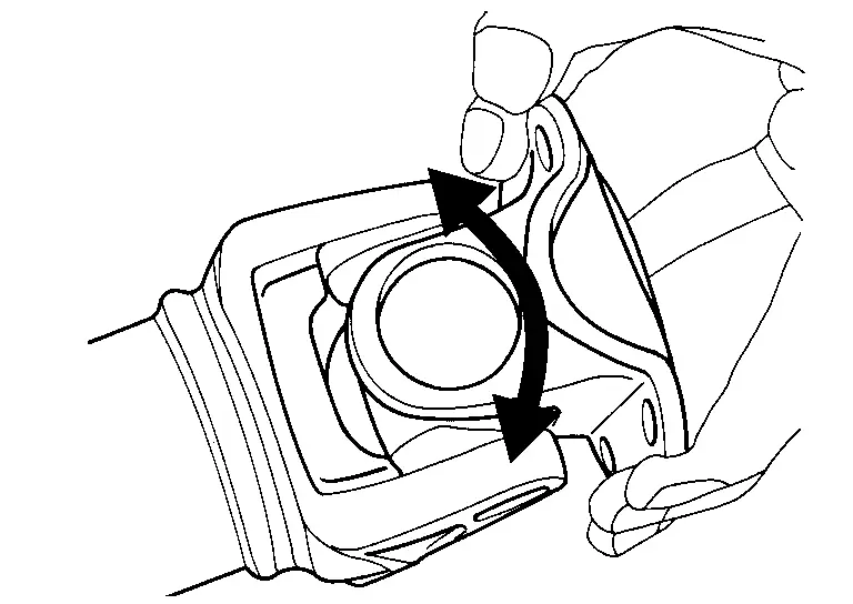
| Joint flex torque | : Refer to Journal. |
NOTE:
The joint flex torque may not be satisfied soon after the assembly.
Check the journal axial play. Refer to Inspection.
Inspection
INSPECTION AFTER REMOVAL
Appearance
Check propeller shaft tube surface for dents or cracks. If malfunction is detected, replace propeller shaft assembly.
Propeller Shaft Runout
Check propeller shaft runout at several points with a dial indicator. If runout exceeds specifications, replace propeller shaft assembly.
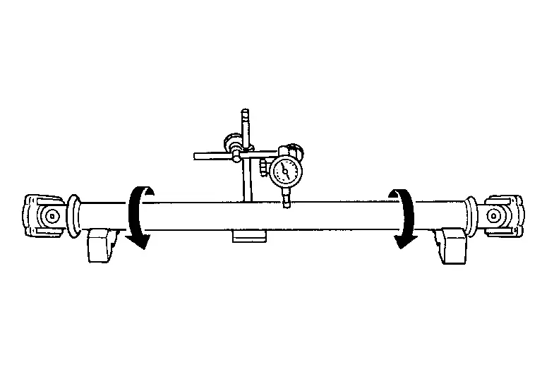
| Propeller shaft runout | : Refer to Propeller Shaft Tube. |
-
Propeller shaft runout measuring point (Point “
 �).
�).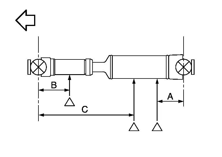
: vehicle front Dimension A : 130 – 150 mm (5.12 – 5.91 in) B : 150 – 180 mm (5.91 – 7.09 in) C : 734.0 mm (28.90 in)
Journal Axial Play
As shown in the figure, while fixing yoke on one side, check axial play of joint. If the journal axial play exceeds the specification, repair or replace the journal parts.
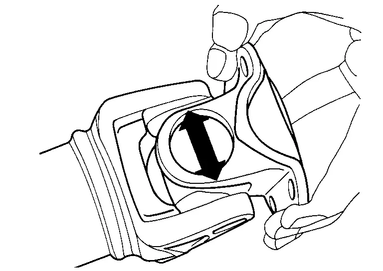
| Journal axial play | : Refer to Journal. |
Joint Flex Torque
Check that the journal moves smoothly and is below the joint flex torque specification. If the joint flex torque exceeds the specification, repair or replace the journal parts.
| Joint flex torque | : Refer to Journal. |
INSPECTION AFTER INSTALLATION
Other materials
Supplemental air bag warning labels
The Nissan Armada is equipped with clearly visible warning labels related to
the supplemental front-impact air bag system. These labels are strategically placed
within the vehicle to remind occupants of critical safety precautions.
SRS air bag
The warning labels 1 in the Nissan Armada are ...
Intake Sensor
Exploded View
Refer to Exploded View.
Removal and Installation
REMOVALRemove front evaporator. Refer to Removal and Installation.
Disconnect sub harness connector from intake sensor harness connector.
Remove intake sensor harness connector from front case upper.
Remove intake sensor from front ...
Vin Registration
Work Procedure
VIN Registration is an operation to register the VIN in ADAS control unit.CHECK VIN
Check VIN of vehicle and note it. For VIN stamped position, refer to Information About Identification or Model Code .
>>
GO TO 2 .
PERFORM VIN REGISTRATION
With CONSULT
Ignition switch ON.
...