
Nissan Armada 2025-2026 Service and Repair Manual: Removal & Installation
WARNING:
REMOVAL
Remove engine cover. Refer to Removal and Installation.
Remove front under cover using a power tool (commercial service tool). Refer to Removal and Installation.
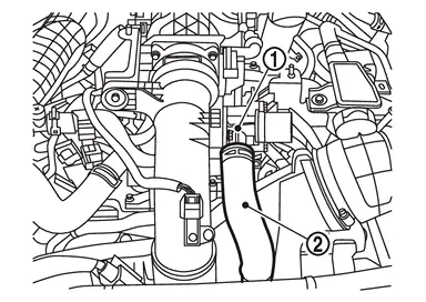
Remove air inlet tube 1 and air inlet tube 2 of charge air cooler side as follows.Remove mounting bolt  of air inlet tube 1
  .
.
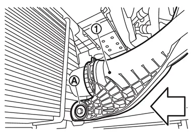
 | : Vehicle front |
 of air inlet tube 1 in the direction of the arrow (
 ) to release the lock.
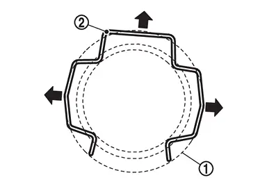
of air inlet tube 2 .
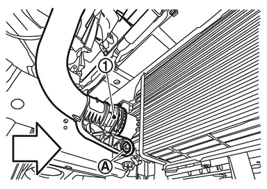
| : Vehicle front |
of air inlet tube 2 in the direction of the arrow () to release the lock.
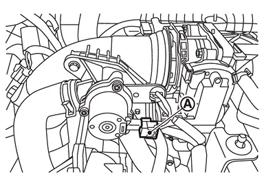
Remove air inlet tube 2 on the electric throttle control actuator side as follows.Disconnect turbocharger boost sensor harness connector .
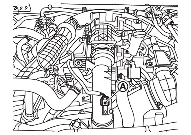
.
from recirculation valve .
of air inlet tube 2 .
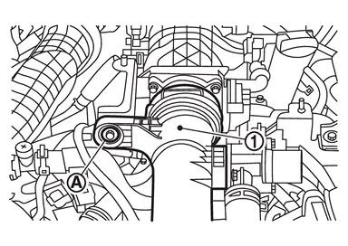
of air inlet tube 1 in the direction of the view arrow () to release the lock.
Remove air inlet tube 1 of turbocharger (bank 1 side) and turbocharger (bank 2 side) as follows.Remove mounting bolt from air inlet tube 1 .
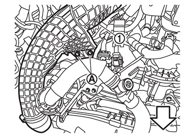
| : Engine front |
from air inlet tube 1 .
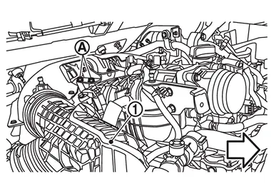
| : Engine front |
from air inlet tube 1 .
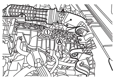
of air inlet tube 1 in the direction of the view arrow () to release the lock.
from turbocharger (bank 1 side) .
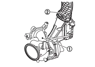
of air inlet tube 1 in the direction of the view arrow () to release the lock.
from turbocharger (bank 2 side) .
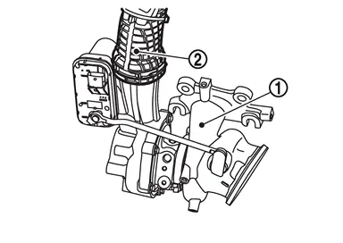
Remove charge air cooler as follows.
 NOTE:
NOTE:
If only remove the charge air cooler, there is no need to remove the air inlet tube (1 and 2). Charge air cooler can be remove by disconnect the connection between the air inlet tubes (1 and 2) and the charge air cooler.
Remove front grille.OFF ROAD MODELS: Refer to Removal and Installation.
CITY MODELS: Refer to Removal and Installation.
OFF ROAD MODELS: Refer to Removal and Installation.
CITY MODELS: Refer to Removal and Installation.
and remove bracket 1 and bracket 4 .
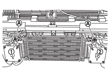
.
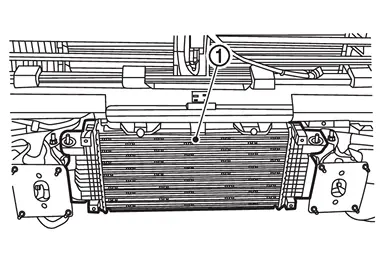
INSTALLATION
Note the following, and install in the reverse order of removal.
Air inlet tube 1 and air inlet tube 2 connections lock with an audible “click� when plugged in.
 Exploded View
Air inlet tube 1 Bracket 1 Mounting rubber (upper) Bracket 2 Charge air cooler cover Clip Mounting rubber (lower) Bracket 3 Bracket 4 Air inlet tube 2 Air inlet hose Clamp Recirculation ...
 Inspection
INSPECTION AFTER REMOVAL
Check air passages of charge air cooler core and fins for clogging, leaks or defo rmation.
Clean or replace charge air cooler if necessary.
Be careful not to deform core fins. ...
Other materials:
Location of Plastic Parts
EXTERIOR
FOR PRO-4X GRADE
Component Material Component Material Door mirror cover ABS Rear spoiler Upper PC + ABS Door mirror finisher ABS Lower ASA Door mirror housing assembly ABS Roof antenna Without ProPILOT Assist 2.1 models Inner cover PC + ABS Door mirror base cover ABS ...
Diagnosis Procedure
Automatic brake hold function does not operate when the operating conditions are satisfied.
PERFORM SELF-DIAGNOSIS (CHASSIS CONTROL MODULE)
With CONSULT
Perform self-diagnosis for “CHASSIS CONTROL�.
Is DTC detected?
YES>>
Check the DTC. Refer to DTC Index.
NO>>
GO TO 2.
CHECK AUTOM ...
NVH Troubleshooting Chart
SUSPECTED PARTS
(Possible cause) Symptom Reference Transfer fluid leakage Noise TRANSFER FLUID (Level low) 1 Inspection TRANSFER FLUID (Wrong) 4 2 TRANSFER FLUID (Level too high) 1 LIQUID GASKET (Damaged) 2 Exploded View OIL SEAL (Worn or damaged) 2 Front oil seal: Exploded View
Rea ...

0.0059