
Nissan Armada 2025-2026 Service and Repair Manual: Removal & Installation
WARNING:
REMOVAL
WARNING:
Be sure to read Refer to PRECAUTION FOR HANDLING HIGH PRESSURE FUEL SYSTEM. when working on the high pressure fuel system.
Put a “CAUTION: FLAMMABLE� sign in the workshop.
Be sure to work in a well ventilated area and furnish workshop with a CO2 fire extinguisher.
Never smoke while servicing fuel system. Keep open flames and sparks away from the work area.
Release fuel pressure. Refer to Work Procedure.
Remove engine cover. Refer to Removal and Installation.
Remove air cleaner cover and air duct. Refer to Removal and Installation.
Remove air inlet tube 1. Refer to Removal & Installation.
Remove intake manifold. Refer to intake manifold : Removal and Installation.
Remove fuel tube (bank 1). Refer to Removal and Installation.
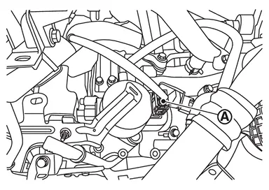
Disconnect high pressure fuel pump harness connector  .
.
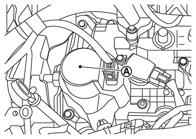
Remove high pressure fuel pump insulator .
Disconnect quick connector with the following procedure :
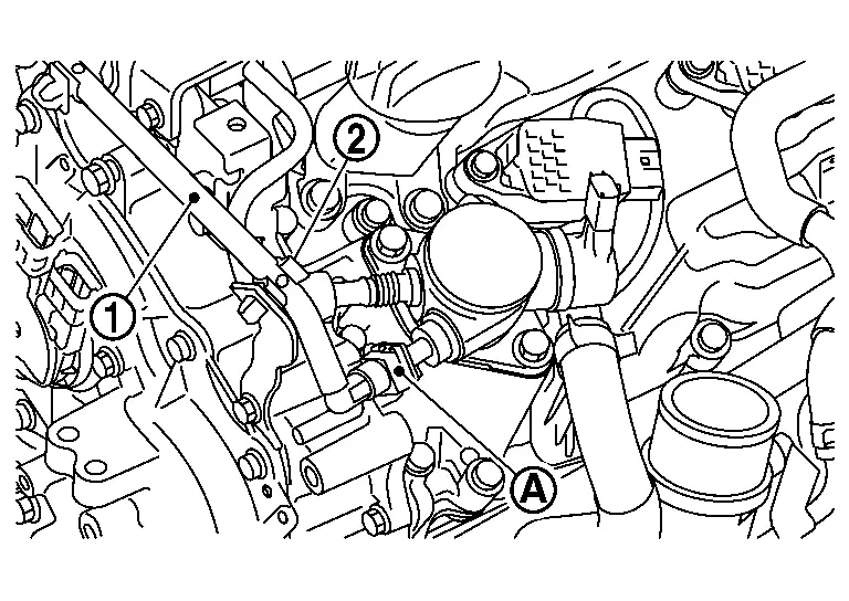
 from holder
  . Disengage and pull up
  the pawl of the fuel feed hose connector retainer
  to disconnect the fuel feed hose from high pressure fuel pump.
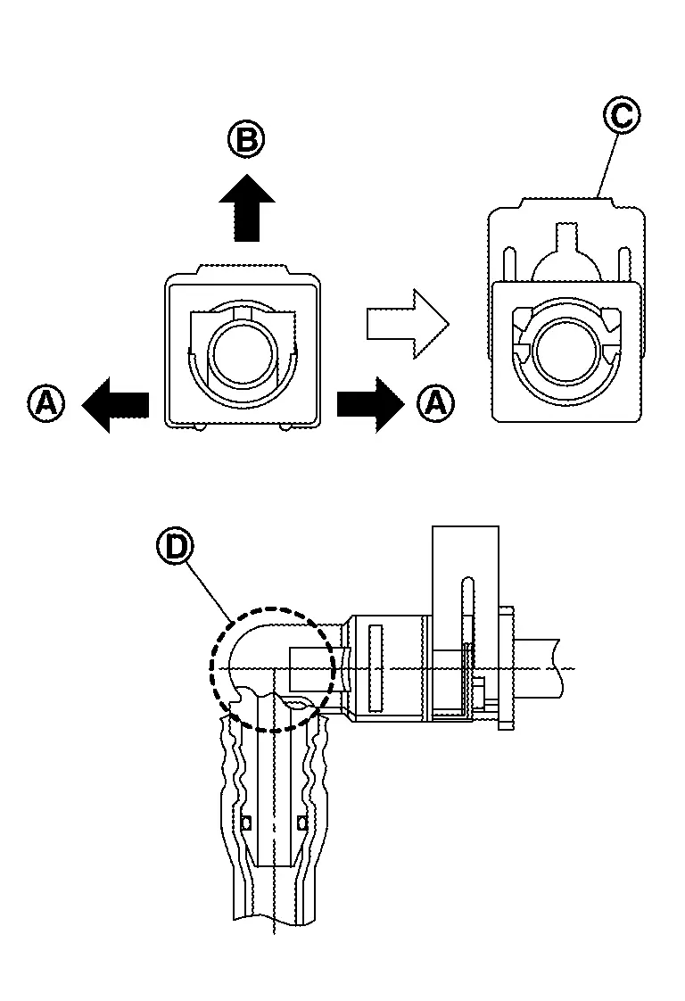
 NOTE:
NOTE:
If the fuel feed hose is stuck, hold the fuel pipe by hand and disconnect it by pushing and pulling.
CAUTION:
Keep parts away from heat source. Especially, be careful when welding is performed around them.
Never expose parts to battery electrolyte or other acids.
Never bent or twist connection between quick connector and fuel feed hose (with damper) during installation/removal.
Pull quick connector holding
 .
.Never remove the retainer.
Prepare a tray and waste beforehand as fuel leaks out.
Never pull with lateral force applied. O-ring inside quick connector may be damaged.
Retainer color : Red To prevent damage to each joint and protect it from the entry of foreign matter, cover the joint with plastic bag
or an equivalent.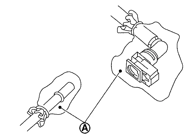
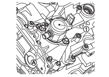
Remove high pressure fuel pump and lifter.
CAUTION:
To prevent damage to high pressure fuel pump and camshaft bracket, loosen bolt alternately by one turn at a time until the reaction force applied on the high pressure fuel pump disappears.
INSTALLATION
CAUTION:
Do not reuse O-rings.
To prevent damage to parts due to generated abnormal stress and eccentric load, always observe the installation procedure.
Install high pressure fuel pump according to the following procedure.Check the orientation of pump cam from the mounting area (view arrow) of high pressure fuel pump.
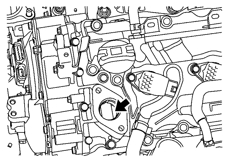
| : Camshaft (EXH) |
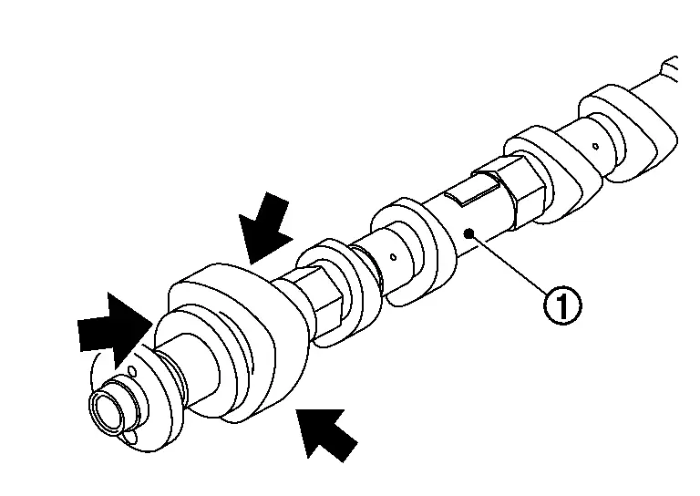
NOTE:
For BDC area, anywhere within the area indicated by arrow can be accepted.
Install O-ring to high pressure fuel pump. When handing new O-ring, paying attention to the following caution items:CAUTION:
Do not reuse O-ring.
Handle O-ring with bare hands. Never wear gloves.
Lubricate O-ring with new engine oil.
Never clean O-ring with solvent.
Check that O-ring and its mating part are free of foreign material.
Never damage O-ring with tools and fingernails during the installation. In addition, twisting or stretching O-ring is not allowed. If O-ring is stretched during the installation to high pressure fuel pump, never install high pressure fuel pump immediately.
CAUTION:
Temporarily tighten bolt
by hand. Alternately tighten bolt by one turn at a time until high pressure fuel pump reaches camshaft bracket.: High pressure fuel pump After a pump flange sitting, tighten the bolts to the specified torque.
Length of screw thread Specified torque 25 mm (0.98 in) : 26.5 N·m (2.7 kg-m, 20 ft-lb)
Connect fuel feed hose with the following procedure, and them install the fuel feed hose.Check no foreign substances are deposited in and around matching pipe and quick connector, and no damage on them. Quick connector shall be inserted gradually, aligning with the axis of the matching pipe. Insert the retainer until it clicks and check the retainer is locked. After insertion, pull the connector and check that the connector is locked.
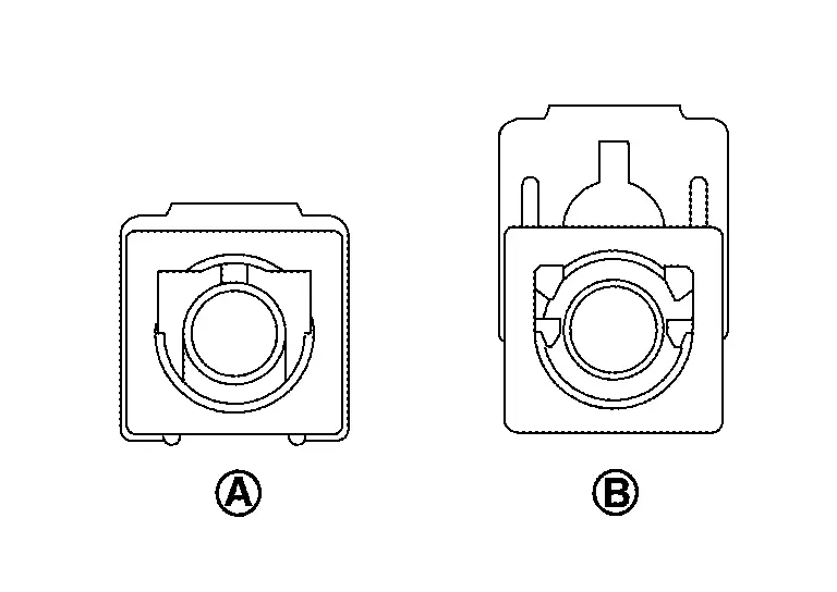
| : Lock position |
| : Unlock position |
CAUTION:
If retainer cannot be installed smoothly, quick connector may be have not been installed correctly. Check connection again.
After attaching the quick connector and fix the hose to the clamp.Install in the reverse order of removal after this step.
 Exploded View
CAUTION:
Never remove or disassemble parts unless instructed as shown in the figure.
High pressure fuel pump insulator High pressure fuel pump O-ring High pressure fuel pump lifter Bracket Hold ...
 Inspection
INSPECTION AFTER INSTALLATION
Check for Fuel Leakage
Turn ignition switch “ON� (with the engine stopped). With fuel pressure applied to fuel piping, check that there is no fuel leakage at connecti ...
Other materials:
Removal and Installation
REMOVAL
Remove outside seat cushion finisher outer. Refer to Disassembly and Assembly.
Disengage massage switch harness fixing clip.
: Clip
Remove fixing screws and then remove massage switch.
INSTALLATION
Install in the reverse order of removal. ...
Precautions for Removing Battery Terminal
NOTE:
NOTE:
NOTE:
The removal of 12V battery may cause a DTC detection error.
HOW TO DISCONNECT 12V BATTERY TERMINAL
Disconnect 12V battery terminal according to instruction described below.
Open the hood.
Turn ignition switch to the ON position.
Turn ignition switch to the OFF position with the d ...
How to turn off the VDC system
The Nissan Armada should normally be driven with the Vehicle Dynamic Control
(VDC) system activated, as it plays a critical role in maintaining stability, traction,
and overall vehicle control in a wide range of driving conditions.
However, in certain situations—such as when the Nissan Armada ...

0.0062