
Nissan Armada 2025-2026 Service and Repair Manual: Removal & Installation
WARNING:
REMOVAL
Remove valve timing control covers (bank 1 and bank 2) and gasket as follows:Disconnect valve timing oil control solenoid valve (bank 1 and bank 2) harness connector. Loosen valve timing control cover mounting bolts in the order from 4 to 1 as shown in the figure.
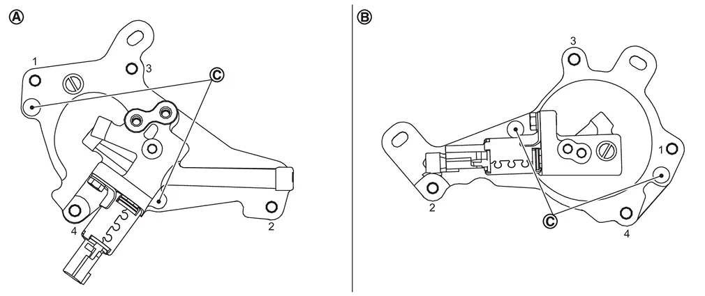
 | : Bank 1 |
 | : Bank 2 |
 | : Dowel pin hole |
CAUTION:
Shaft is internally jointed with camshaft sprocket center hole. When removing, keep it horizontal until it is completely disconnected.
Shaft is engaged with camshaft sprocket center hole on inside. Pull straight out so as not to tilt until the joint is disengaged. Remove O-ring from the shaft of the valve timing control covers (bank 1 and bank 2). Remove exhaust valve timing control solenoid valve and seal ring if necessary.Remove electric intake valve timing control actuator (bank 1 and bank 2) as follows:Disconnect electric intake valve timing control actuator harness connector. Remove mounting bolts for the electric intake valve timing control actuator (bank 1 and bank 2).
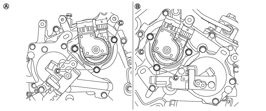
| : Bank 1 |
| : Bank 2 |
INSTALLATION
 NOTE:
NOTE:
If an electric intake valve timing control actuator removed, carry out the teach of “Idle Air Volume Learning�. Refer to Work Procedure.
Install valve timing control covers (bank 1 and bank 2) as follows:Install new seal rings  in shaft grooves .
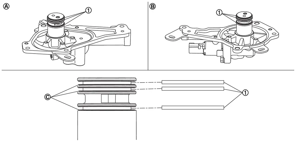
| : Bank 1 |
| : Bank 2 |
CAUTION:
When replacing seal ring, replace all rings with new one.
Install camshaft sprocket cover in the following procedure.Apply a liquid gasket (equivalent to ThreeBond 1217H) to the camshaft sprocket cover as shown in the illustration, so that the start and end of the coating overlap.
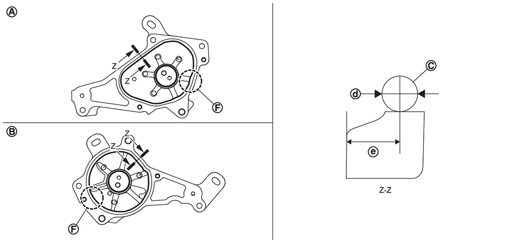
: Bank 1 : Bank 2 : Liquid gasket 
: φ2.7 - 3.7 mm (0.106 - 0.146 in) 
: 4.0 - 5.6 mm (0.157 - 0.220 in) 
: (Overlap) 5.0 mm (0.197 in)
CAUTION:
Align the center of both shaft holes of the shaft and the camshaft sprocket, and then insert them.
Be careful not to drop the seal ring from the shaft groove.
Attaching should be done within 5 minutes after liquid gasket application.
Being careful not to move seal ring from the installation groove, align dowel pins on front cover with holes to install valve timing control covers. Tighten camshaft sprocket cover mounting bolts to the torque specified below in the order from 1 to 4 as shown in the figure.
| : Bank 1 |
| : Bank 2 |
| : Dowel pin hole |
 | : 11.3 N·m (1.2 kg-m, 8 ft-lb) |
After all bolts are tightened, tighten No. 1 bolt to the specified torque again.
Install electric intake valve timing control actuator.
Align positions of the electric intake valve timing control actuator (bank 1 and bank 2) with the position of the intake camshaft sprocket and install the electric intake valve timing control actuator.
 Exploded View
Valve timing control cover (bank 1) Seal ring Electric intake valve timing control actuator (bank 1) Valve timing oil control solenoid valve (bank 1) O-ring Valve timing oil control solenoid v ...
 Front Cover
...
Other materials:
Removal and Installation
REMOVAL
Remove the steering column cover upper. Refer to Removal and Installation.
Disconnect the driver monitor camera connector.
Remove the driver monitor camera mounting screws , and remove the driver monitor camera from the steering column cover upper .
INSTALLATION
Installation is in the rev ...
Examination of Panel
Irregularities in the panel must be examined carefully to see whether or not they can be repaired, and also to determine the most suitable repair method.
Refer to "Examination of Panel Damage".
Work Direction on a Vehicle
1 Area mainly accessed from the back to the front 2 Area mainly accessed ...
Exploded View
Windshield molding Dam sealant rubber upper Clip Insulator Dam sealant rubber Spacer Windshield glass Roof panel Adhesive Painted surface primer Glass primer Body side outer panel Dash panel : Bracket : Inside mirror base : Edge : R end : Always replace after every disassembly.
...

0.0052