
Nissan Armada 2025-2026 Service and Repair Manual: Removal and Installation
WARNING:
WARNING:
Be sure to read Refer to PRECAUTION FOR HANDLING HIGH PRESSURE FUEL SYSTEM.when working on the high pressure fuel system.
Put a “CAUTION: FLAMMABLE� sign in the workshop.
REMOVAL
Release fuel pressure. Refer to Work Procedure.
Disconnect battery cable from the negative terminal.
Remove engine cover. Refer to Removal and Installation.
Remove air cleaner assembly. Refer to Removal and Installation.
Remove charge air cooler. Refer to Removal & Installation.
Remove intake manifold. Refer to Removal and Installation.
Remove fuel tube 1 and 2.
CAUTION:
Because fuel leakage occurs, prepare a tray, shop cloth, and other items in advance.
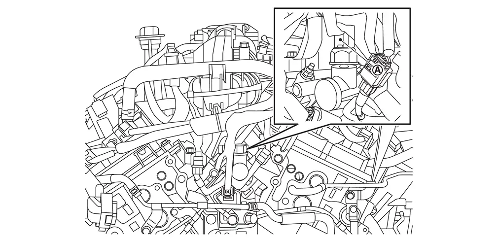
Disconnect fuel rail pressure sensor harness connector  .
.
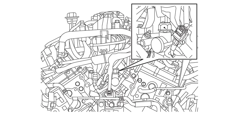
Disconnect fuel injector harness connector.
Remove fuel rail pressure sensor  if necessary.
Follow steps below to remove the fuel injector.Remove fuel rail (bank 1) , fuel rail (bank 2)  in this order.
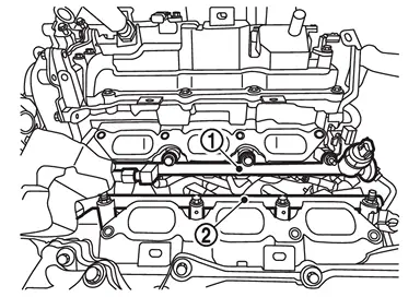
and fuel injector assembly. (bank1 and bank 2)
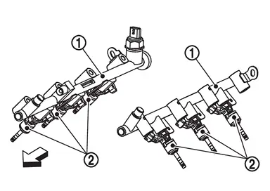
 | : Engine front |
CAUTION:
Be careful that no parts interfere with the fuel injectors.
Because fuel leakage occurs, prepare a tray, shop cloth, and other items in advance.
If the fuel rail and fuel injector cannot be removed assembly, follow the steps below to remove them.
Remove fuel injector from cylinder head as per the following.
CAUTION:
Be careful with remaining fuel that may go out from fuel rail.
Be careful not to damage injector nozzles during removal.
Never bump or drop fuel injector.
Never disassemble fuel injector.
Remove injector holder.
Install an remover [SST: KV101296S0 ( — )] (A) to the injector connector side so that cutout
 of injector remover faces the injector connector side.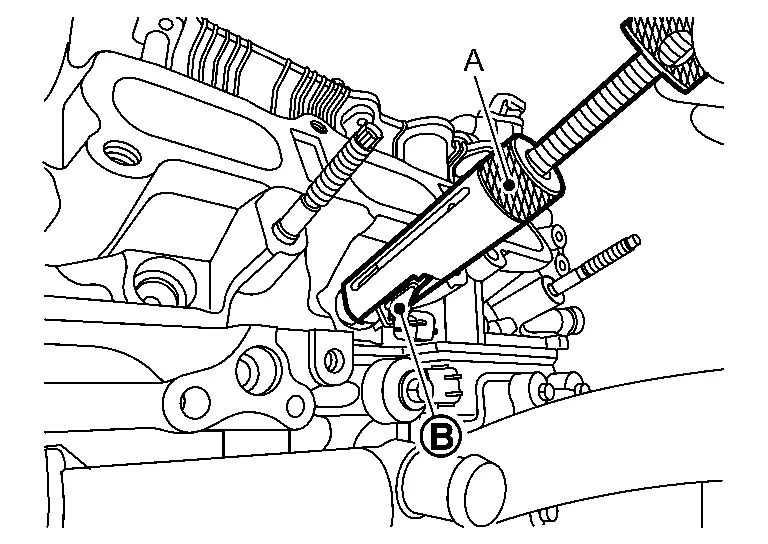
Hook pawl portion
of injector remover [SST: KV101296S0 ( — )] (A) to groove portion  of injector.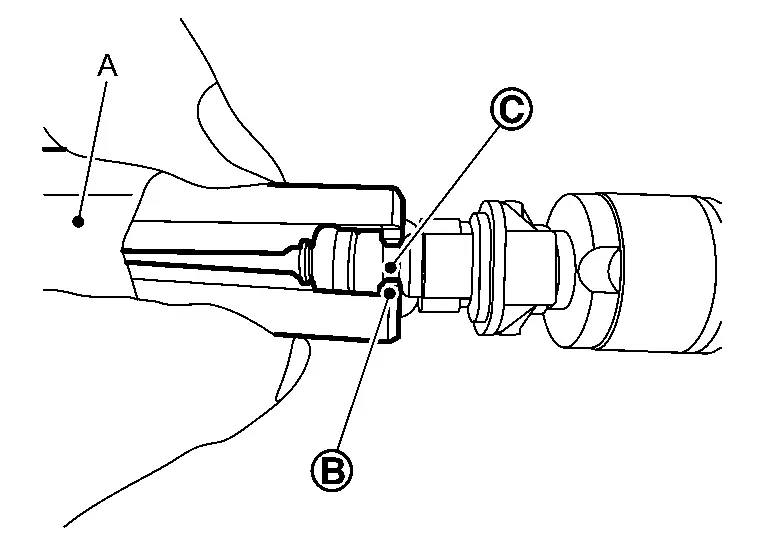
Press down body portion of injector remover [SST: KV101296S0 ( — )] (A) until it contacts cylinder head.
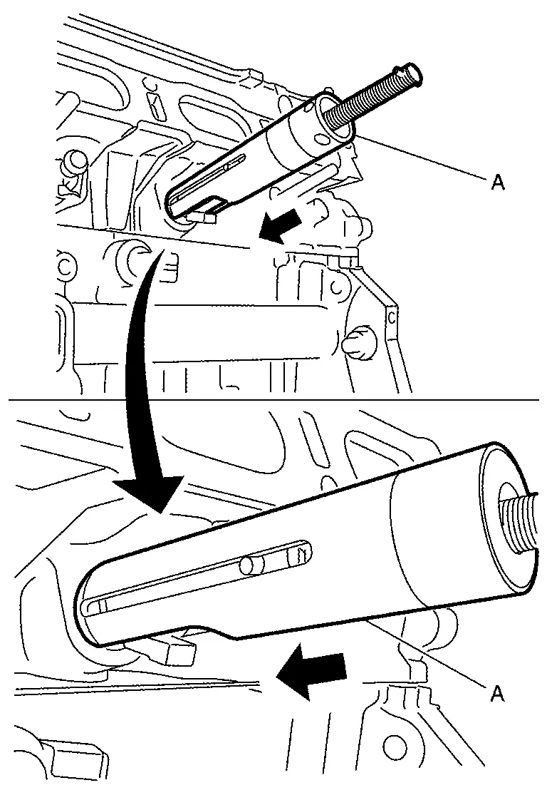
Tighten injector remover [SST: KV101296S0 ( — )] clockwise and remove injector from cylinder head.
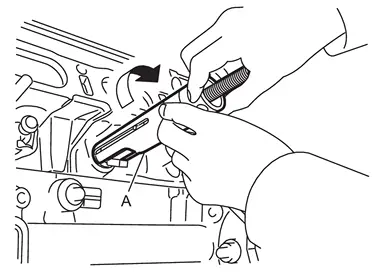
Pinch the seal ring
and cut it off. Never scratch the fuel injector.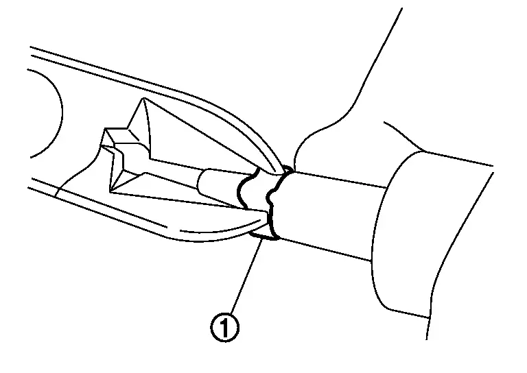
INSTALLATION
After removing fuel pressure sensor, install fuel pressure sensor according to the instructions below:Fix fuel rail in a vice.
CAUTION:
Never scratch or crack fuel rail during work procedure.
Apply engine oil to the entire perimeter of the fuel pressure sensor screw and the tip.CAUTION:
Check that fuel rail and fuel pressure sensor screw have no damage, foreign matter, or stains.
Temporarily tighten fuel pressure sensor.
 | : 10.0 N·m (1.0 kg-m, 89 in-lb) |
CAUTION:
Before tightening fuel pressure sensor, securely install a hexagon tool.
Never use impact applied fuel pressure sensor or gasket, such as dropped.
| Tightening angle : | 35° |
CAUTION:
To check tightening angle, use angle wrench [SST: KV10112100 (BT-8653-A)]. Never judge the angle by visual inspection.
The torque value for the angle tightening must be 60 N·m (6.1 kg-m, 44 ft-lb) or less.
If torque value reaches 60 N·m (6.1 kg-m, 44 ft-lb), then replace fuel rail and pressure sensor with a new one.
Install seal ring to fuel injector using the following procedure:
CAUTION:
Handle seal ring with bare hands. Do not wear gloves.
Do not apply engine oil to seal ring.
Do not clean seal ring with solvent.
Point the injector mark
side of the injector seal drift [SST:KV10119990 ( — )] (A) in the direction of the fuel injector and insert the injector seal drift in to the fuel injector. 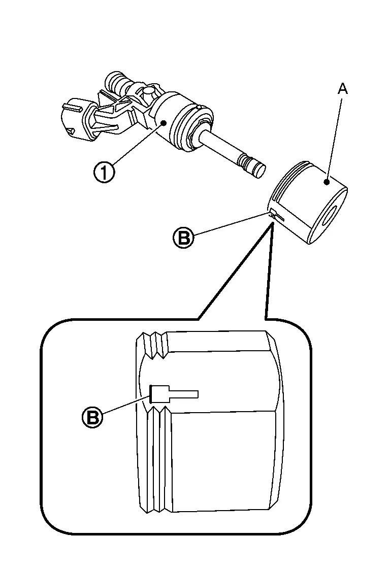
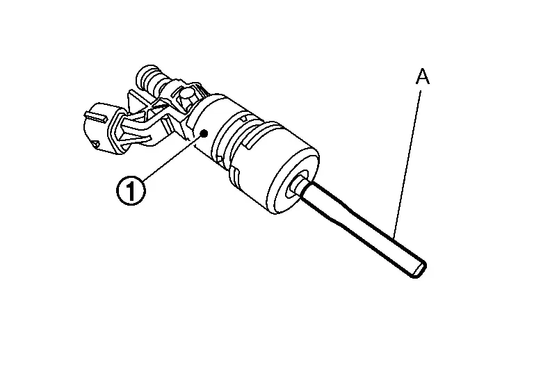
Install seal guide [SST: KV10119990 ( — )] (A) to fuel injector
.
Set seal ring
into seal guide [SST:KV10119990 ( — )] (A).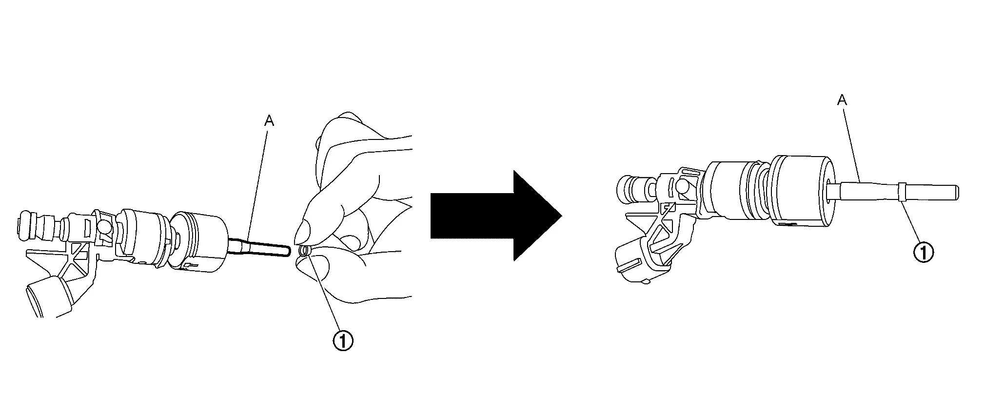
Set seal installer [SST:KV10119990 ( — )] (A) into seal guide [SST:KV10119990 ( — )] (B).
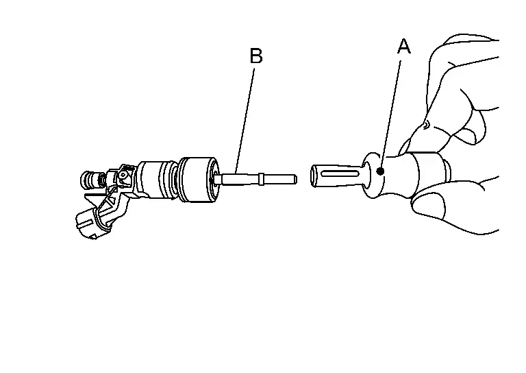
Install seal ring
to the fuel injector by pushing it in, in the direction of the arrow with seal installer (A).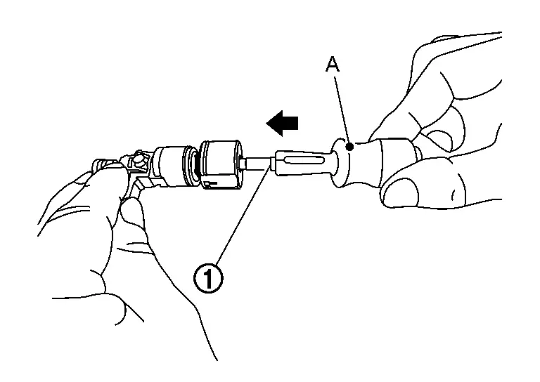
CAUTION:
Be careful that seal ring does not exceed the groove portion of fuel injector.
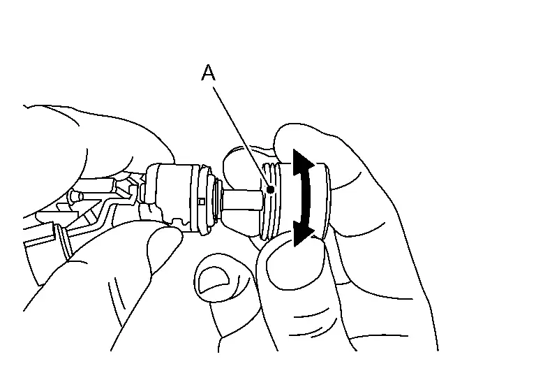
Rotate clockwise and counterclockwise by 90° while pressing seal ring to fit it by injector seal drift [SST:KV10119990 ( — )] (A).
 NOTE:
NOTE:This is done to correct any elongation of the seal ring caused by installation and for preventing sticking when inserting fuel injector into cylinder head.
Note the following points and install the O-ring and backup ring to the fuel injector.
CAUTION:
Be sure to handle the O-ring with bare hands. (Never wear gloves.)
Apply engine oil to the O-ring.
Never use solvents or similar substances when cleaning the O-ring seal.
Check that the O-ring and its mating part are free of foreign material.
When installing O-ring, never scratch it with tool or fingernail. Also never twist or stretch O-ring. If O-ring is stretched while being attached, never insert it immediately.
Insert O-ring straight onto fuel tube. Never decenter or turn it.
Both fuel injector
and the backup ring have a tapered cross section shape. Therefore, be careful of the orientation when installing them.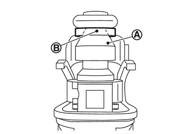
Install fuel injector to fuel rail as per the following:
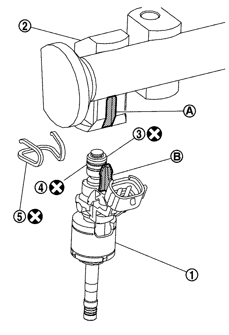
 | : O-ring (black) |
 | : Backup ring |
 to fuel injector.
CAUTION:
Never reuse fuel injector holder. Replace it with a new one.
Be careful to keep fuel injector holder from interfering with O-ring. If interference occurs, replace O-ring.
Insert it while matching it to the axial center.
Insert so that protrusion
of fuel injector is aligned to cutout .
Check that protrusions of fuel injectors and fuel rail are aligned with cutouts of clips after installation.
Install the fuel injector (bank1 and bank 2 ) into the cylinder head installation hole.
CAUTION:
Be careful to prevent contact with the end of the injector nozzle.
Tighten mounting bolts and nuts in two steps in the order from 1 to 4 shown in the figure.
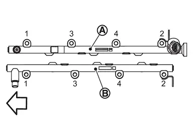
: Engine front 1st step : 10.0 N·m (1.0 kg-m, 89 in-lb) 2nd step  : 22.0 N·m (2.2 kg-m, 16 ft-lb)
Connect the fuel rail pressure sensor harness connector.
Connect the fuel injector harness connector.
Install fuel tube according to the following procedure :
CAUTION:
Never use fuel tube if its terminal tip is damaged.
Observe the tightening order and the tightening torque.
Fuel tube 1
Apply engine oil to the following parts.
NOTE:Check that there is no foreign matter adhering to the engine oil application area.
Contact surface of the high-pressure fuel pump
Contact surface of fuel rail
Temporarily tighten flare nuts fuel tube 1.
Tighten the flare nut
on fuel tube 1 to the specified torque.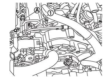
: 15.0 N·m (1.5 kg-m, 11 ft-lb) Tighten the flare nut
on fuel tube 1 to the specified torque.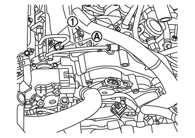
: 15.0 N·m (1.5 kg-m, 11 ft-lb) Tighten the flare nut
on fuel tube 1 to the specified torque.: 38.0 N·m (3.9 kg-m, 28 ft-lb) Tighten the flare nut
on fuel tube 1 to the specified torque.: 38.0 N·m (3.9 kg-m, 28 ft-lb)
Fuel tube 2
Apply engine oil to the following parts.
NOTE:Check that there is no foreign matter adhering to the engine oil application area.
Contact surface of the high-pressure fuel pump
Contact surface of fuel rail
Temporarily tighten flare nuts fuel tube 1.
Temporarily tighten the fuel tube 2
mounting bolts . 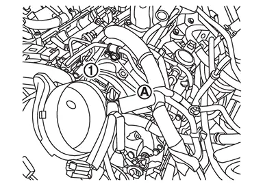
Tighten the flare nut
on fuel tube 2 to the specified torque.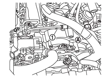
: 15.0 N·m (1.5 kg-m, 11 ft-lb) Tighten the flare nut
on fuel tube 2 to the specified torque.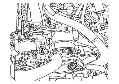
: 15.0 N·m (1.5 kg-m, 11 ft-lb) Tighten the fuel tube 2
mounting bolt to the specified torque.: 25.0 N·m (2.6 kg-m, 18 ft-lb) Tighten the flare nut
on fuel tube 2 to the specified torque.: 38.0 N·m (3.9 kg-m, 28 ft-lb) Tighten the flare nut
on fuel tube 2 to the specified torque.: 38.0 N·m (3.9 kg-m, 28 ft-lb)
Install removed parts in the reverse order of removal.
 Exploded View
CAUTION:
Never disassemble or remove components beyond the configuration shown in the figure.
Fuel rail pressure sensor Fuel rail (bank 1) Stud bolt Fuel tube insulator Fuel tube 2 Fuel tube 1 ...
 Inspection
INSPECTION AFTER INSTALLATION
Fuel Leakage Inspection
Check for fuel leakage according to the following procedure.
Turn ignition switch ON (with engine stopped). With fuel pressure applied to fuel pip ...
Other materials:
Glue System
Glue systems allow pulling when an area is not easily accessible like roof rail or beneath braces. It is also one of the easiest systems to learn. But it is mainly limited to soft dents.
A couple of things that affect the glue pulling:
Temperature
The diameter and the size of the pull knob
Applica ...
Disassembly and Assembly
DISASSEMBLY
Remove inside and outside seat cushion finisher outer. Refer to Disassembly and Assembly.
Disengage seatback board fixing retainer .
With 4way power seat system
With 8way power seat system
Disengage seat cushion trim fixing retainers .
With 4way power seat system
With 8way power se ...
Exploded View
Engine mounting bracket (RH) Engine mounting insulator (RH) Stopper bracket (RH) Engine mounting bracket (LH) Engine mounting insulator (LH) Stopper bracket (LH) Engine mounting insulator (rear) Comply with the assembly procedure when tightening. Refer to Unit Removal & Installation. ...

0.0057