
Nissan Armada 2025-2026 Service and Repair Manual: Removal and Installation
WARNING:
REMOVAL
Bank 1 side
Remove front tire assembly (RH). Refer to ROAD WHEEL TIRE : Removal & Installation.
Remove fender protector (RH). Refer to Removal and Installation.
Remove main muffler. Refer to EXHAUST SYSTEM : Removal & Installation.
Remove 2nd catalyst converter (bank 1)  .
.
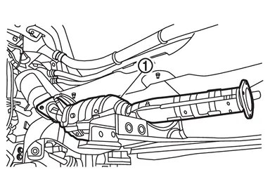
Using the heated oxygen sensor wrench [SST: KV10117100 (NI-3647-A)], remove heated oxygen sensor (bank 1), if necessary.
Remove catalyst converter support bracket (bank 1) from A/T side  .
.
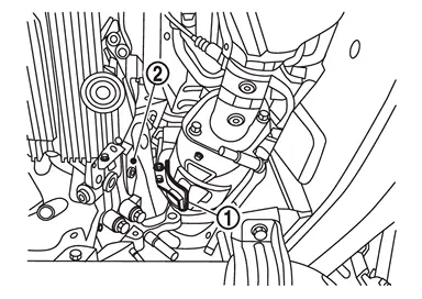
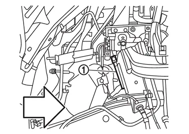
Remove mounting nut of 12V sub battery (lithium ion battery) harness 1. Refer to Exploded View.
Remove 12V sub battery (lithium ion battery) harness 1 bracket .
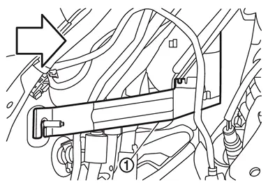
 | : Vehicle front |
Using the heated oxygen sensor wrench [SST: KV10117100 (NI-3647-A)], remove air fuel ratio (A/F) sensor (bank 1) .
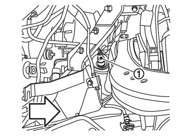
| : Vehicle front |
Remove heat insulator (upper). Refer to Removal & Installation.
Remove clamp (bank 1) .
| : Vehicle front |
Remove catalyst converter (bank 1).
Bank 2 side
Remove front tire assembly (LH). Refer to ROAD WHEEL TIRE : Removal & Installation.
Remove fender protector (LH). Refer to Removal and Installation.
Remove main muffler. Refer to EXHAUST SYSTEM : Removal & Installation.
Remove 2nd catalyst converter (bank 2) .
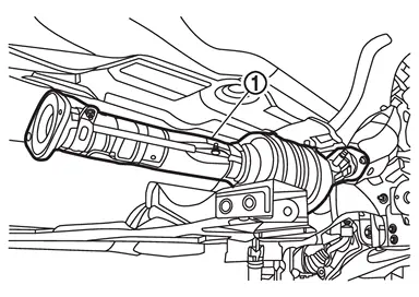
Using the heated oxygen sensor wrench [SST: KV10117100 (NI-3647-A)], remove heated oxygen sensor (bank 2), if necessary.
Remove front propeller shaft (4WD models). Refer to Removal and Installation.
Remove catalyst converter support bracket (bank 2) from A/T side .
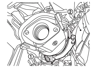
Disconnect the connection between the lower shaft and the lower joint. Refer to Removal and Installation.
Remove heat insulator (upper). Refer to Removal & Installation.
Using the heated oxygen sensor wrench [SST: KV10117100 (NI-3647-A)], remove air fuel ratio (A/F) sensor (bank 2) .
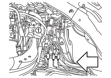
| : Vehicle front |
Remove clamp (bank 2) .
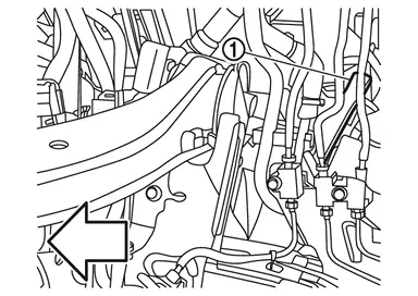
| : Vehicle front |
Remove catalyst converter (bank 2).
INSTALLATION
Install in the reverse order of removal.
 NOTE:
NOTE:
If a heated oxygen sensor is replaced, carry out the teach of “Idle Air Volume Learning�. Refer to Work Procedure.
If an air fuel ratio (A/F) sensor is replaced, carry out the teach of “Idle Air Volume Learning�. Refer to Work Procedure.
CAUTION:
To install catalyst converter, the positioning against turbocharger is necessary. For this reason, the following instructions must be complied with.
Clean up on the gasket touching surface.
Temporarily install catalyst converter to turbocharger.
NOTE:
To install, turn clamp and bolt several turns, being careful not to drop parts.
Temporarily install 2nd catalyst converter to catalyst converter.
NOTE:
To install, turn bolt and nut several turns, being careful not to drop parts.
Temporarily install main muffler to 2nd catalyst converter.
NOTE:
To install, turn nut several turns, being careful not to drop parts.
Temporarily tighten the bolt and nut of temporarily-tightened parts.
NOTE:
Tighten bolt and nut until they fit to the parts.
Temporarily tighten mounting bolt  of main muffler
  .
.
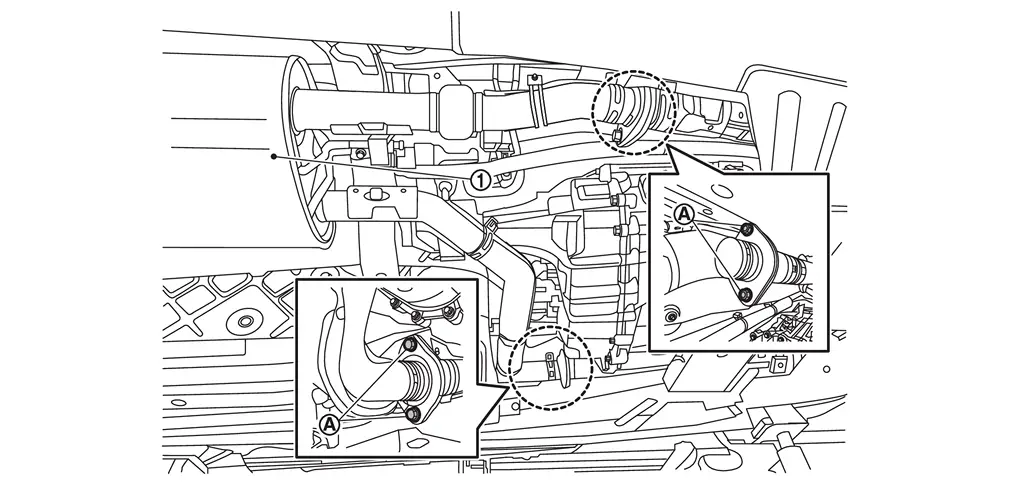
Temporarily tighten mounting bolts and mounting nuts  of catalyst converter (bank 1 and bank 2).
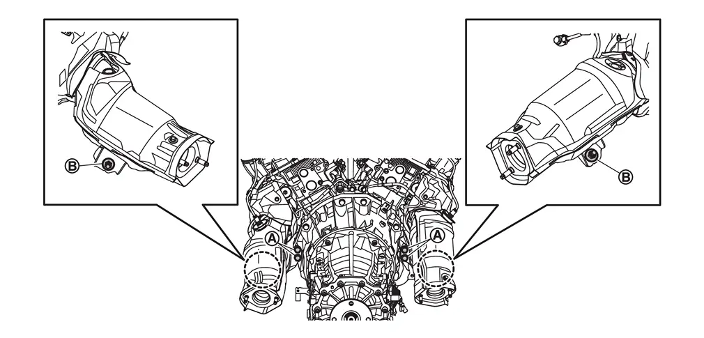
Temporarily install 2nd catalyst converter (bank 1 and bank 2) using the following steps.Temporarily tighten mounting nuts  and
and  .
.
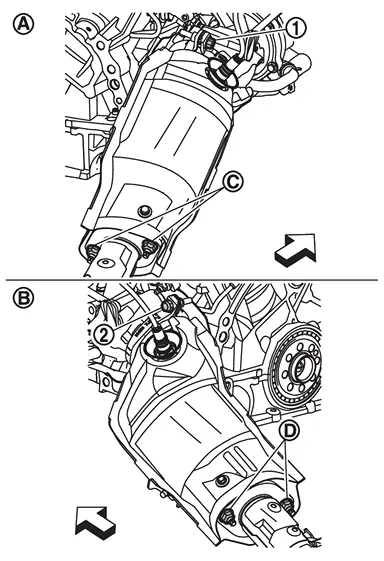
| : Clamp (bank 1) |
 | : Clamp (bank 2) |
| : Bank 1 |
| : Bank 2 |
| : Vehicle front |
CAUTION:
To install, position the turbocharger assembly marking line within the range of the width and  of clamp as shown in the figure.
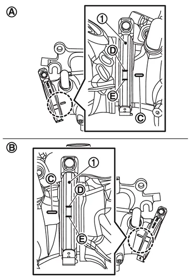
| : Bank 1 |
| : Bank 2 |
Tighten the temporarily tightened bolts and nuts to the specified torque, according to the following step:Tighten clamp (bank 1).
| : Clamp (bank 1) |
| : Clamp (bank 2) |
| : Bank 1 |
| : Bank 2 |
| : Nut (bank 1) |
| : Nut (bank 2) |
| : Vehicle front |
and mounting nut of catalyst converter support bracket (bank 1 and bank 2) to specified torque.
of main muffler to specified torque.
 Exploded View
Clamp (bank 1) Gasket 1 (bank 1) Catalyst converter (bank 1) Catalyst converter support bracket (bank 1) Air fuel ratio (A/F) sensor (bank 1) Gasket 2 (bank 1) 2nd catalyst converter (bank 1) ...
 Inspection
INSPECTION AFTER REMOVAL
Surface Distortion
Check the surface distortion of the catalyst converter mating surface (turbocharger side) with a straigtedge (A) and a feeler gauge (B).
Limit 0.15 mm (0 ...
Other materials:
Sandpaper Grits
Select a sandpaper with a grit, appropriate to the putty used. Sanding marks that occur due to sanding are removed with further sanding.
SWITCHING TO A SANDPAPER OF A DIFFERENT GRIT
Sanding marks that occur during sanding are sanded with a sandpaper of the next finer grit. When doing this, do not s ...
Removal and Installation
REMOVAL
Remove rear door finisher. Refer to Removal and Installation.
Remove rear door inside handle fixing screws .
Remove rear door inside handle fixing pawls, and then remove rear door inside handle.
:Pawl
INSTALLATION
Note the following items, and then install in the reverse order of re ...
Work Flow
OVERALL SEQUENCE
DETAILED FLOW
INTERVIEW FOR MALFUNCTION
Interview the symptom to the customer.
>>
GO TO 2.
SYMPTOM CHECK
Check the symptom from the customer's information. Check that any symptom occurs other than the interviewed symptom.
Insufficient cooling/heating>>
GO TO 3.
Refr ...

0.0087