
Nissan Armada 2025-2026 Service and Repair Manual: Removal and Installation
WARNING:
REMOVAL
Remove valve timing control covers (bank 1 and bank 2). Refer to Removal & Installation.
Remove electric intake valve timing control actuator (bank 1 and bank 2). Refer to Removal & Installation.
Remove crankshaft pulley. Refer to Removal & Installation.
Remove front cover. Refer to Removal & Installation.
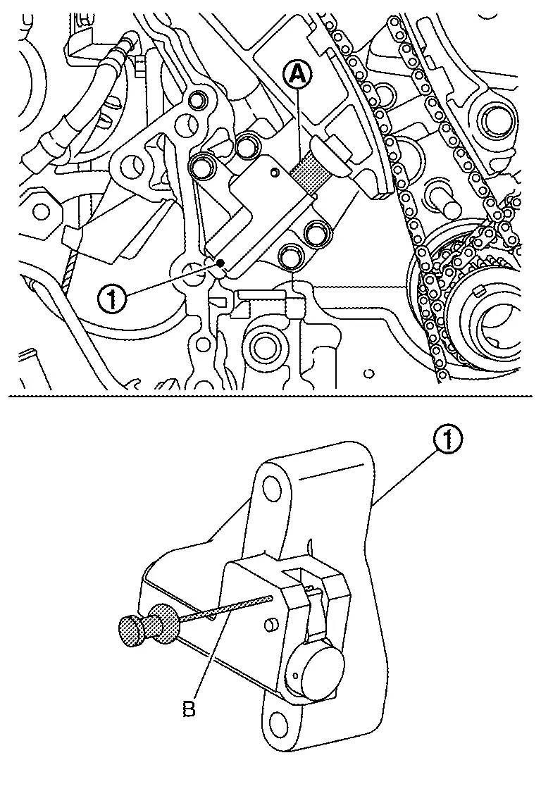
Remove timing chain tensioner as follows:Insert plunger  into tensioner
  .
.
Remove timing chain tension guides and slack guides.
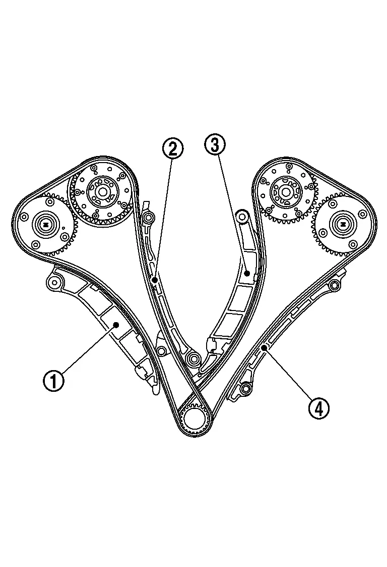
| : Timing chain slack guide (bank 1) |
 | : Timing chain tension guide (bank 1) |
 | : Timing chain guide (bank 2) |
 | : Timing chain tension guide (bank 2) |
Remove timing chain (bank 1 and bank 2) .
Remove oil pump drive chain if necessary.
INSTALLATION
CAUTION:
Do not reuse O-rings.
 NOTE:
NOTE:
If a timing chain is removed, carry out the teach of “Electric IVT Control Actuator Position Learning�. Refer to Work Procedure.
The below figure shows the relationship between the matching mark on each timing chain and that on the corresponding sprocket, with the components installed.
Install timing chain oil jet, if removed.
CAUTION:
When removing timing chain oil jet, replace timing chain oil jet and cylinder block.
The direction of the timing chain oil jet must be within ±10°
 of the indicated position .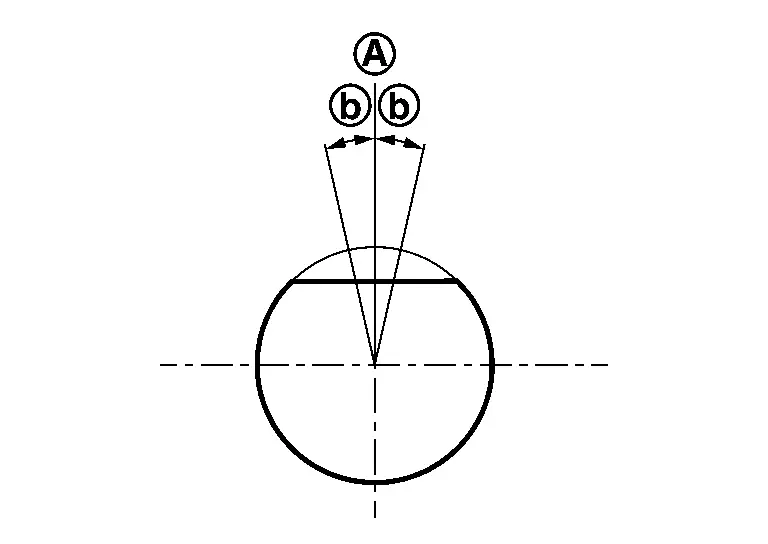
Check that dowel pin and crankshaft key are located as shown in the figure. (No. 1 cylinder at compression TDC)
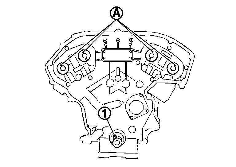
NOTE:
Though camshaft does not stop at the position as shown in the figure, for the placement of cam noses, it is generally accepted camshaft is placed for the same direction of the figure.
| Camshaft dowel pin | |
| : At cylinder head upper face side in each bank. | |
| Crankshaft key | |
| : At cylinder head side of bank 1. | |
Install timing chain as follows:
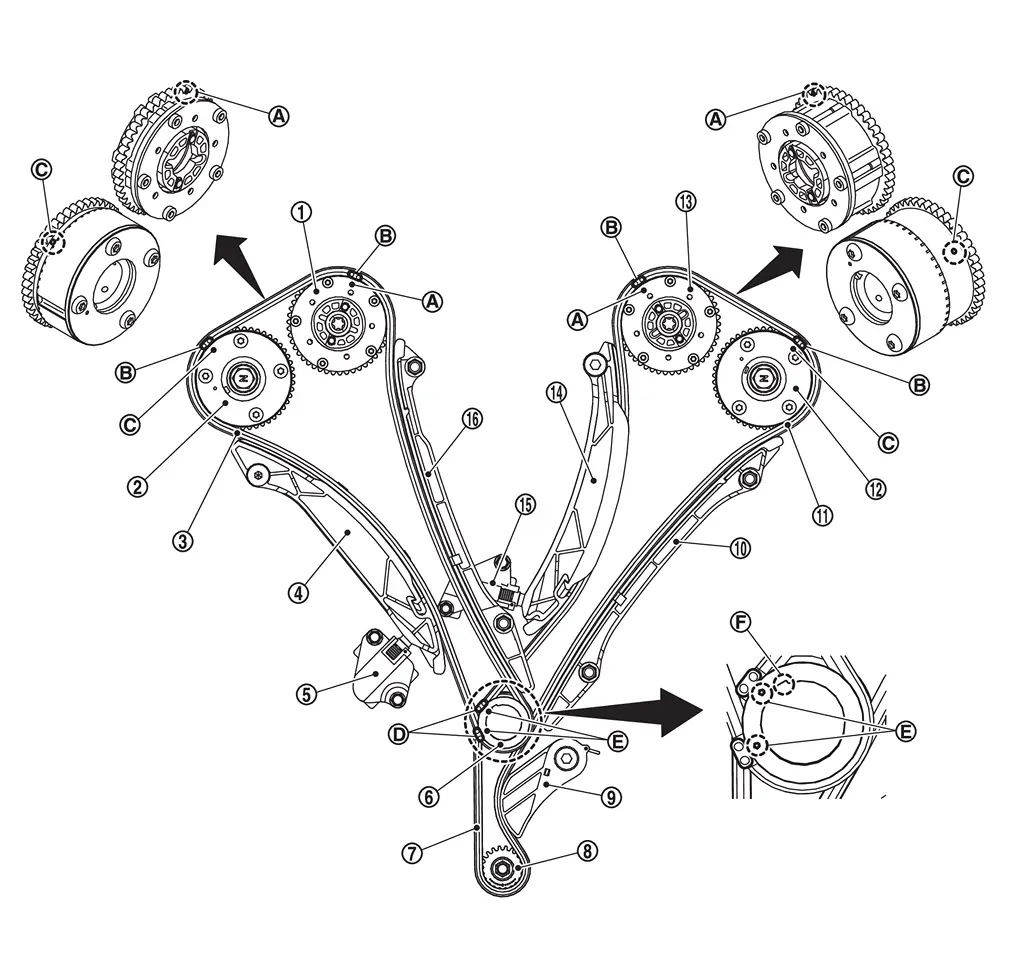
 | Intake camshaft sprocket (bank 1) | | Exhaust camshaft sprocket (bank 1) | | Timing chain (bank 1) |
| Timing chain slack guide (bank 1) |  | Timing chain tensioner (bank 1) |  | Crankshaft sprocket |
 | Oil pump drive chain |  | Oil pump sprocket |  | Oil pump drive chain tensionar |
 | Timing chain tension guide (bank 2) |  | Timing chain (bank 2) |  | Exhaust camshaft sprocket (bank 2) |
 | Intake camshaft sprocket (bank 2) |  | Timing chain slack guide (bank 2) |  | Timing chain tensioner (bank 2) |
 | Timing chain tension guide (bank 1) | ||||
| Matching mark (notched) |  | Matching mark (copper link) |  | Matching mark (notched) |
 | Matching mark (yellow link) |  | Matching mark (notched) |  | Crankshaft key |
Insert crankshaft key
into the crankshaft key groove.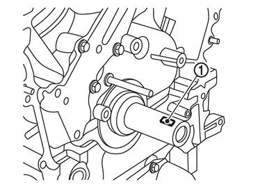
Install crankshaft sprocket
.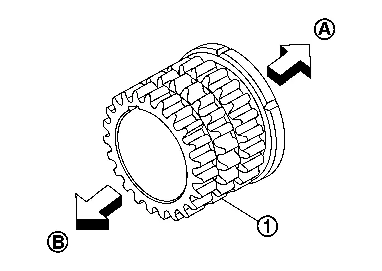
: Engine front : Crankshaft side Check the matching marks on crankshaft sprocket face the front of the engine.
- Install timing chain as follows:
Assemble timing chain in the order of bank 2 - bank 1.
Align matching marks on the camshaft sprocket (INT, EXH) and crank sprocket with the matching marks on the timing chain.
NOTE:If matching marks do not line up, turn the resin coupling at the center of the intake camshaft sprocket.
If timing chain loosens after the timing chain is installed or if the chain guide, slack guide, or chain tensioner cannot be installed, rotate the resin coupling at the center of the intake camshaft sprocket counterclockwise until it hits.
Install timing chain tension guide.
Temporarily timing chain tension guide mounting bolts below in the order from 1 to 2 as shown in the figure.
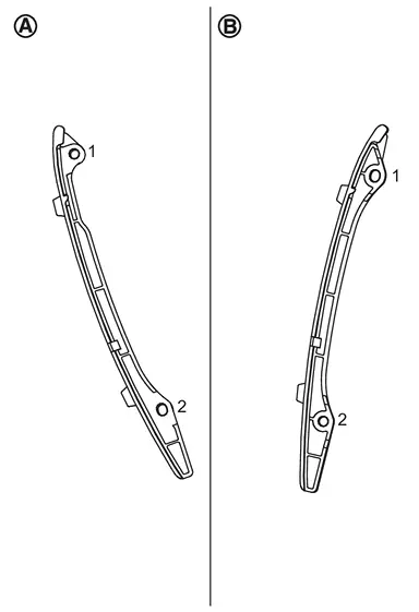
: Bank 1 side : Bank 2 side Tighten timing chain tension guide mounting bolts to the torque specified below in the order from 1 to 2 as shown in the figure.
: Bank 1 side : Bank 2 side 
: 17.7 N·m (1.8 kg-m, 13 ft-lb)
Install timing chain slack guide.
CAUTION:
Never overtighten slack guide mounting bolts . It is normal for a gap to exist under the bolt seats when mounting bolts are tightened to the specification.
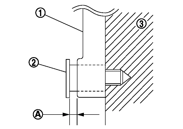
| : Cylinder block |
Install timing chain tensioner.
Disconnect clip from chain tensioner.
Check again that the matching marks on sprockets and timing chain have not slipped out of alignment.
Install front cover. Refer to Removal & Installation.
Install crankshaft pulley. Refer to Removal & Installation.
Install electric intake valve timing control actuator (bank 1 and bank 2). Refer to Removal & Installation.
Install valve timing control covers (bank 1 and bank 2). Refer to Removal & Installation.
 Exploded View
Timing chain (bank 1) Timing chain slack guide (bank 1) Timing chain tension guide (bank 1) Timing chain tensioner (bank 1) Timing chain tensioner (bank 2) Timing chain slack guide (bank 2) Ti ...
 Inspection
INSPECTION AFTER REMOVAL
Timing Chain
Check for cracks and any excessive wear at link plates and roller links of timing chain. Replace timing chain if necessary.
: Crack : Wear
INSPECTION AFTER IN ...
Other materials:
Exploded View
Front door panel Front door outside molding Rear door outside molding Rear door panel : Pawl : Vehicle front ...
Exploded View
Front door glass run Front door panel Front door glass Front door module assembly Hole seal Front door power window motor Front door regulator fastener Front door lower sash : Pawl : Always replace after every disassembly. : N·m (kg-m, in-lb) : Body grease , , : Indicates that the part ...
Basic information
The Nissan Armada is equipped with an advanced automatic brake hold function
designed to enhance driving convenience in stop-and-go traffic conditions. This
system automatically maintains braking force when the vehicle comes to a complete
stop, such as at traffic lights or intersections, allow ...

0.005