Precautions for Body Repair
WARNING:
-
Jacking up or lift up the vehicle may the vehicle height to go down which cause a personal injury and/or damage to the air suspension component parts. Refer to Precaution for when Jacking and Lifting Up the vehicle with Electronic Air Suspension System.
WARNING:
Description
-
Technicians are encouraged to read the Body Repair Manual (Fundamentals) in order to ensure that the original functions and quality of the vehicle are maintained. The Body Repair Manual (Fundamentals) contains additional information, including cautions and warnings, that are not including in this manual. Technicians should refer to both manuals to ensure proper repair.
-
Please note that this information is prepared for worldwide usage, and as such, certain procedures might not apply in some regions or countries.
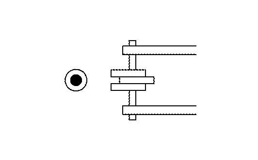
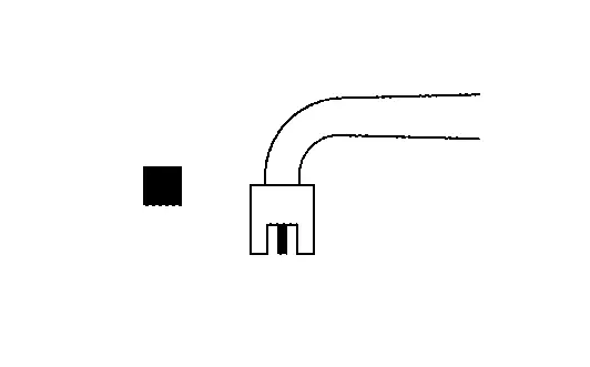
The symbols used in this section for welding operations are shown below.
| Symbol marks | Description | |
|---|---|---|
| ″Number″ |
″Number″ after symbol mark is the total number of welds to apply. Example 1:  ″1″× 20 (0.79) = 1 MIG seam weld by length 20 mm (0.79 in). ″1″× 20 (0.79) = 1 MIG seam weld by length 20 mm (0.79 in). |
|
|
|
2-panel spot weld |
|
|
|
3-panel spot weld | |
|
|
MIG plug weld |
|
|
For 3-panel plug weld method
|
||
|
|
MIG seam weld / Point weld |
|
|
|
Rivet |
|
 ″4″A = 4 MIG plug welds for 3-panel plug weld method.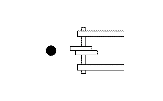
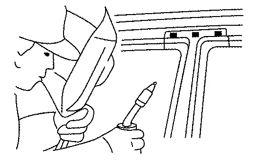
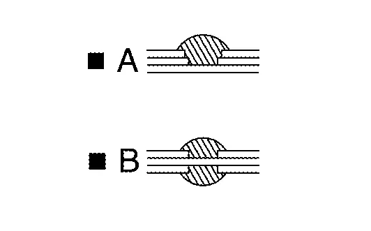
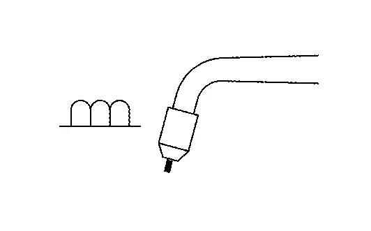
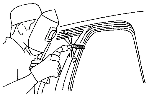
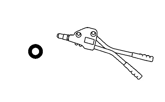
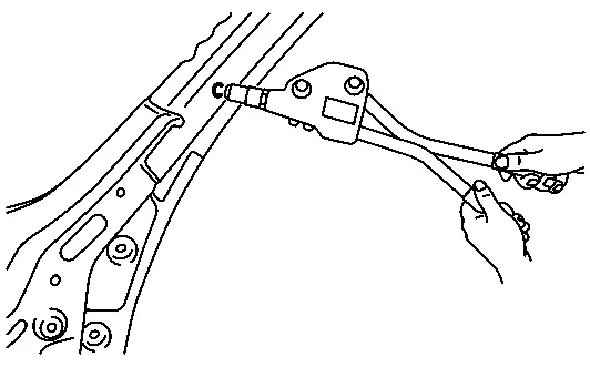
-
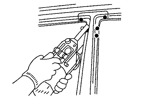
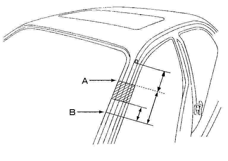
Front pillar butt joint can be determined anywhere within shaded area as shown in the figure. The best location for the butt joint is at position A due to the construction of the vehicle.
-
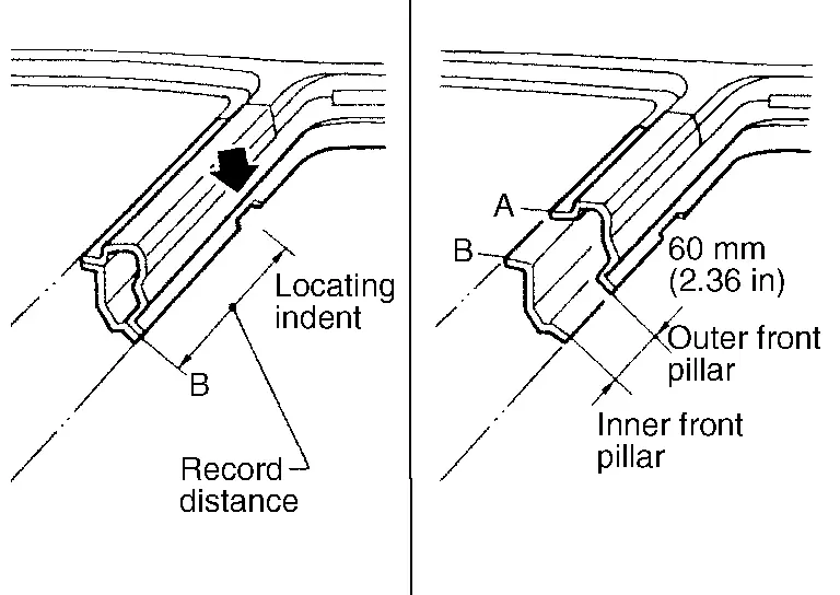
Determine cutting position and record distance from the locating indent. Use this distance when cutting the service part. Cut outer front pillar over 60 mm (2.36 in) above the inner front pillar cut position.
-
Prepare a cutting jig to make outer pillar easier to cut. Also, this will permit the service part to be accurately cut at the joint position.
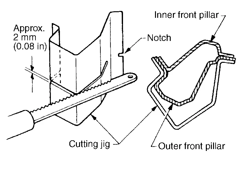
-
An example of cutting operation using a cutting jig is as per the following.
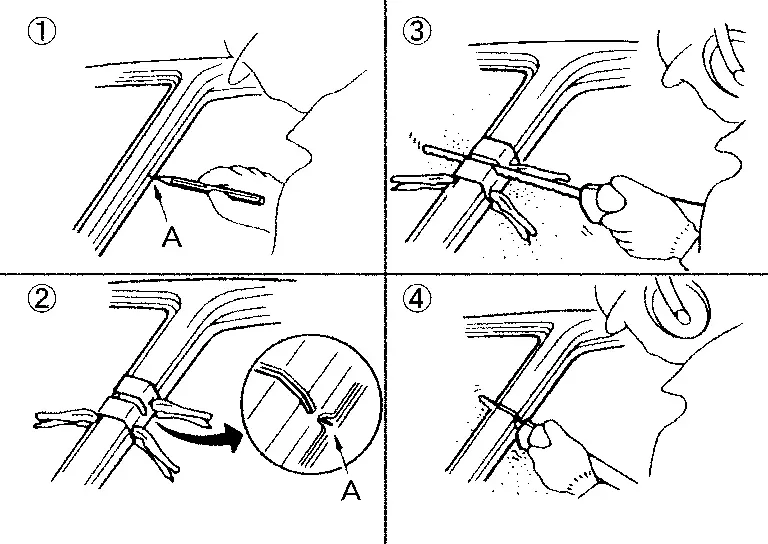
-
Mark cutting lines.
A: Cut position of outer pillar
B: Cut position of inner pillar
-
Align cutting line with notch on jig. Clamp jig to pillar.
-
Cut outer pillar along groove of jig (at position A).
-
Remove jig and cut remaining portions.
-
Cut inner pillar at position B in same manner.
Welding of Ultra High Strength Steel
SPOT WELDING
Spot welding is limited to ultra high strength steel (tensile strength: 980 MPa) according to the welding conditions listed below.
CAUTION:
-
If the below welding conditions cannot be met, then perform plug welding.
-
Never spot weld ultra high strength steel of tensile strength more than 980 MPa. For this type of ultra high strength steel, perform plug welding.
-
The below welding condition is applicable only to this vehicle. Never apply this same welding condition to other vehicles.
| Welder tip diameter | 6 mm |
| Welding pressure (Gun force) | 3300 N |
| Panel configuration | Combination of a plate of tensile strength 980 MPa and that of tensile strength less than 980 MPa. (Up to 3 plates) |
|
Welding current and weld time
|
|
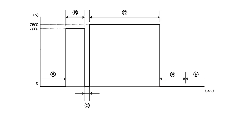
| Welding current | Weld time | Welding pressure (Gun force) | Description | |||
| 50 Hz | 60 Hz | |||||
 |
Before welding | 0 A | - | - | 0 N | - |
 |
First energization | 7000 A |
0.04 sec (2 cycle) |
0.05 sec (3 cycle) |
3300 N | Secure an energization path |
 |
Cool down | 0 A |
0.02 sec (1 cycle) |
0.02 sec (1 cycle) |
3300 N | - |
 |
Second energization | 7500 A |
0.12 sec (6 cycle) |
0.12 sec (7 cycle) |
3300 N | Main energization for nugget formation |
 |
Keep pressurization | 0 A |
0.10 sec (5 cycle) |
0.08 sec (5 cycle) |
3300 N | - |
 |
After welding | 0 A | - | - | 0 N | - |
PLUG WELDING
To weld ultra high strength steel of tensile strength 980 MPa or more, perform plug welding observing the welding hole diameter described in the manual.
CAUTION:
-
To perform plug welding, use fuel mixture (Ar 80% + CO2 20%) for shielding gas of welder.
-
Never use carbon dioxide gas (CO2 100%) as shielding gas of welder. Using CO2 100% gas results in inadequate weld strength.
-
When welding hole diameter cannot be met, make multiple holes (smaller diameter) so that the sum of the hole areas equals the area of the original weld hole.
EXAMPLE
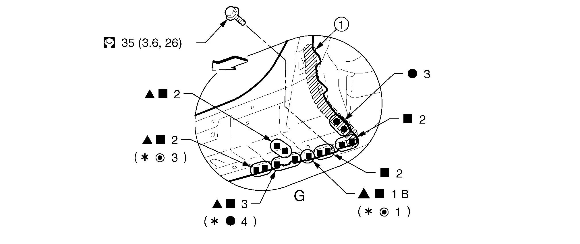
 |
Body sealing | ||||
|
: vehicle front : Drill φ6 mm (0.24 in) hole for the plug welding hole (ultra high strength steel).
 : For spot welding of steel plate of tensile strength 980 MPa, observe the indicated welding conditions. Refer to ″Welding of Ultra High Strength Steel″. : For spot welding of steel plate of tensile strength 980 MPa, observe the indicated welding conditions. Refer to ″Welding of Ultra High Strength Steel″. |
|||||
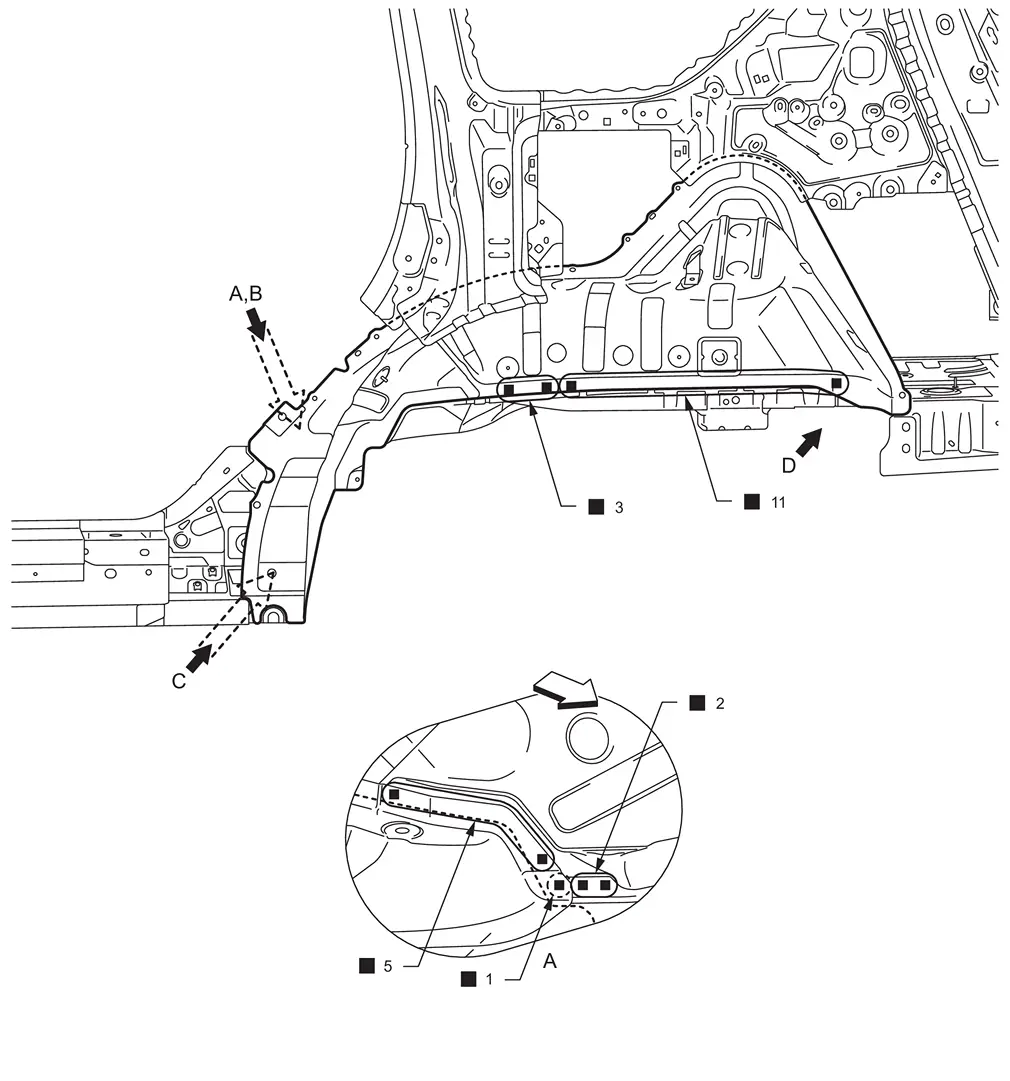
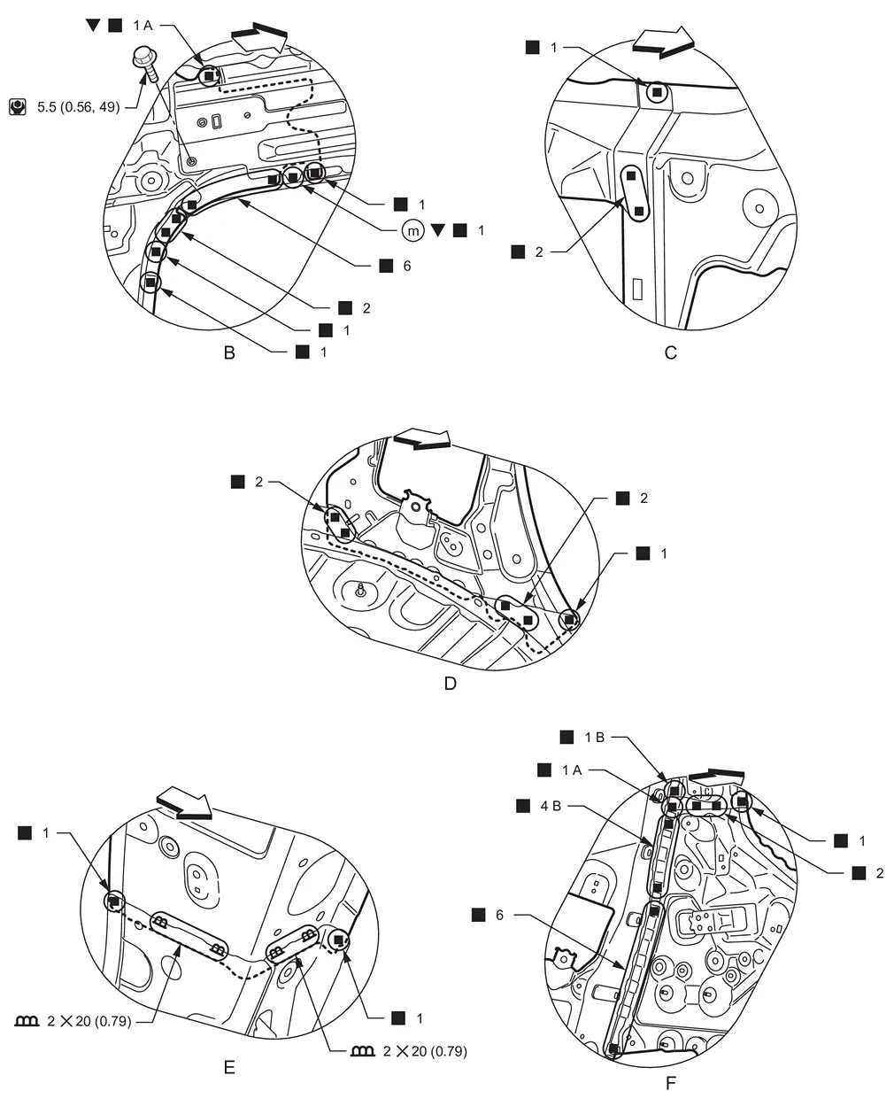
Side Radiator Core Support
WARNING:
-
Jacking up or lift up the vehicle may the vehicle height to go down which cause a personal injury and/or damage to the air suspension component parts. Refer to Precaution for when Jacking and Lifting Up the vehicle with Electronic Air Suspension System.
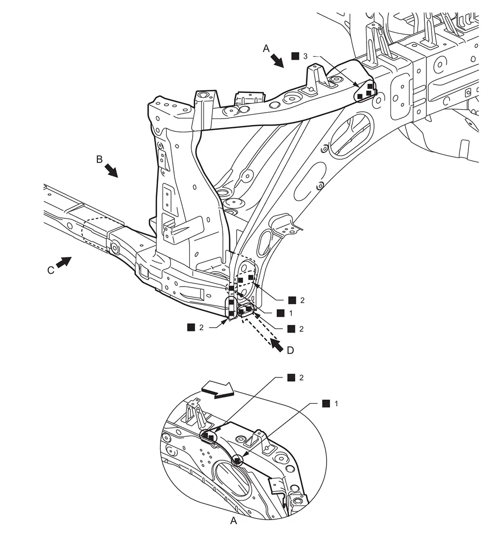
|
: vehicle front  : Weld the parts onto the back of the component part. : Weld the parts onto the back of the component part. |
|||||
| Replacement part | |||||
| • | Side radiator core support | ||||
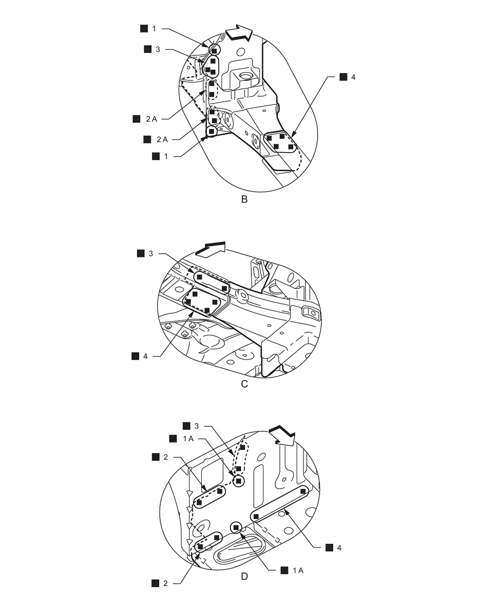
|
: vehicle front : Weld the parts onto the back of the component part. |
Radiator Core Main Support
WARNING:
-
Jacking up or lift up the vehicle may the vehicle height to go down which cause a personal injury and/or damage to the air suspension component parts. Refer to Precaution for when Jacking and Lifting Up the vehicle with Electronic Air Suspension System.
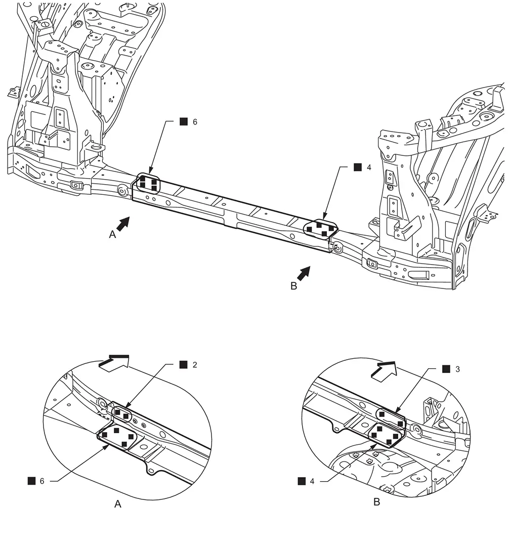
| : vehicle front | |||||
| Replacement part | |||||
| • | Radiator core main support assembly | ||||
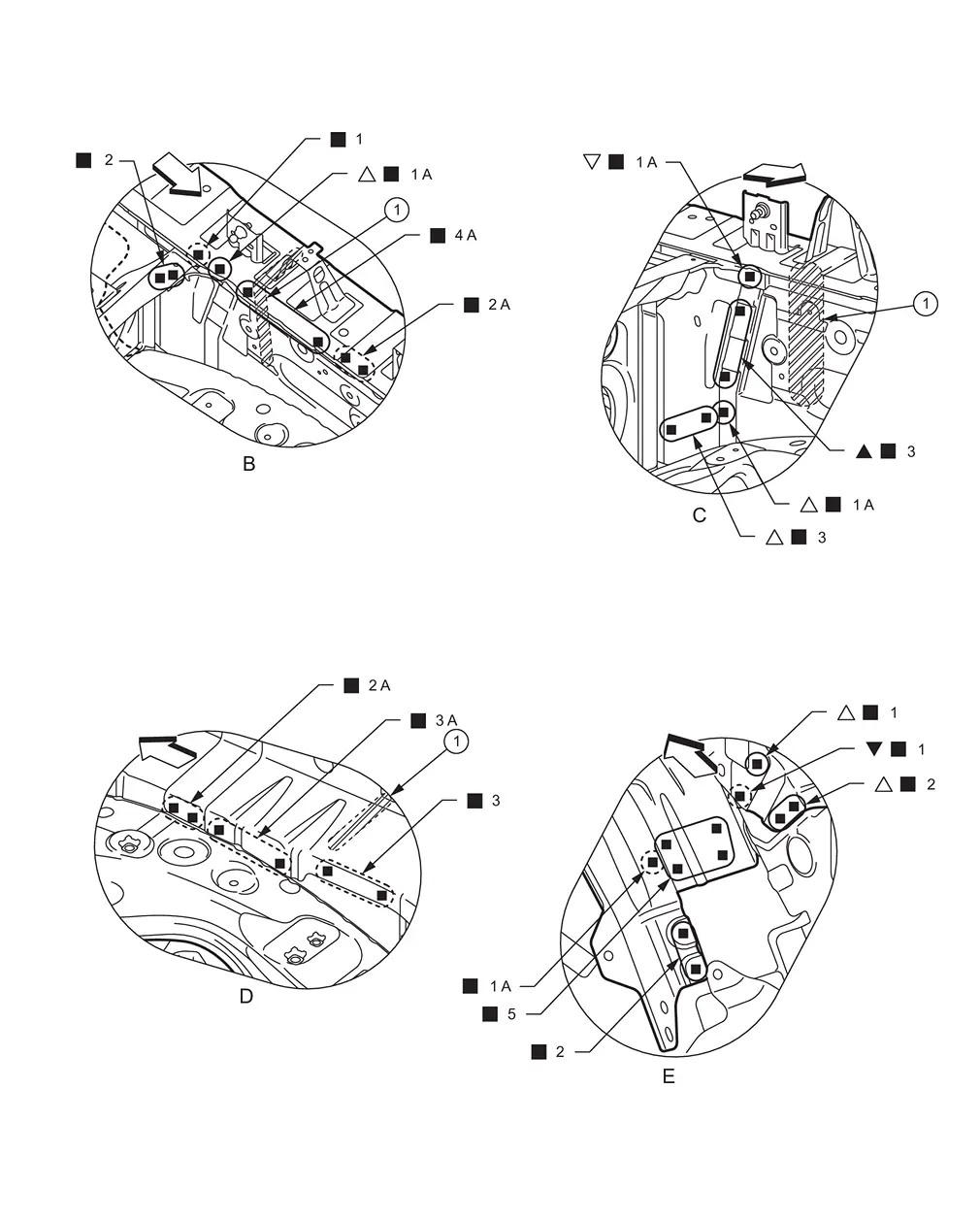
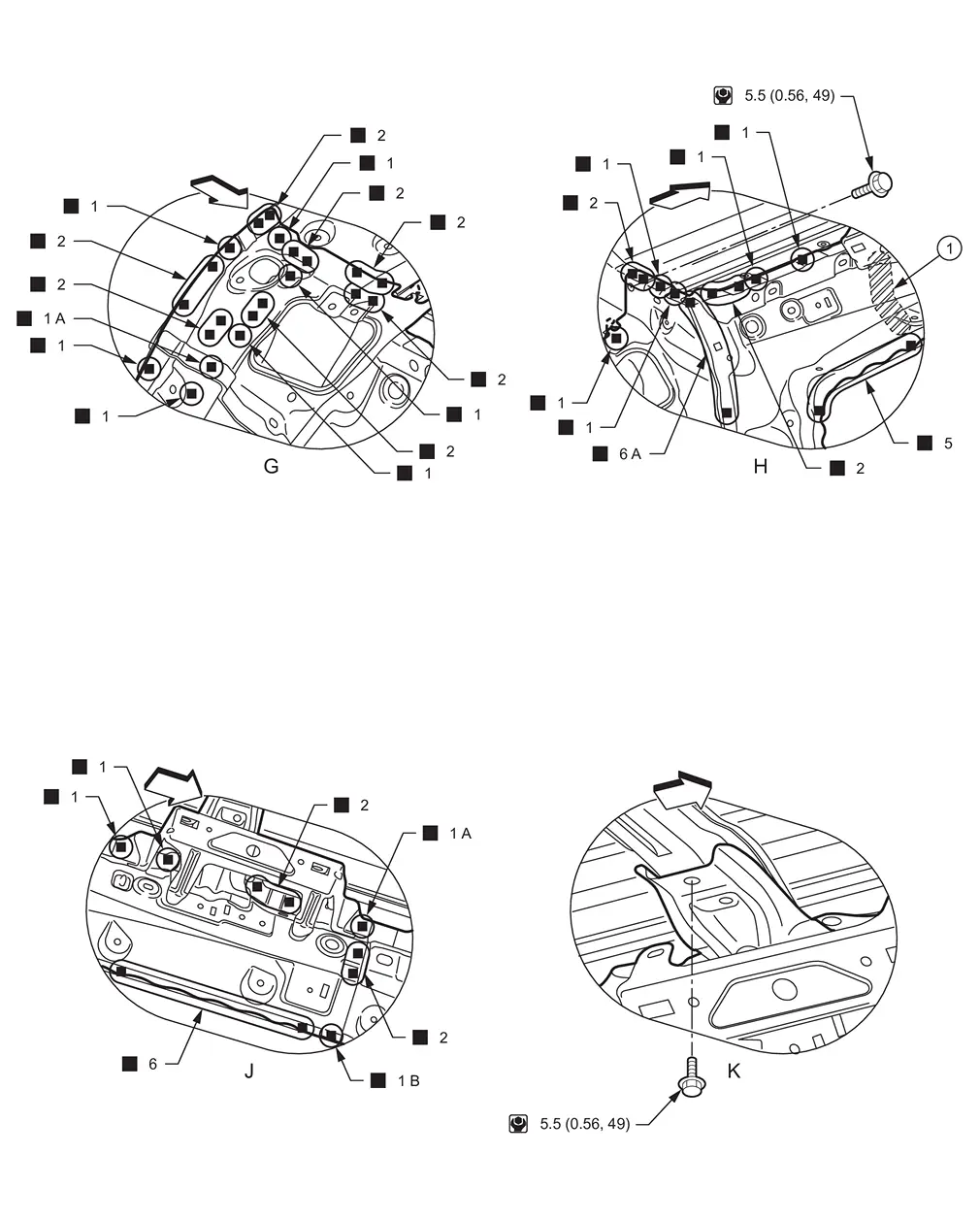
Hoodledge
WARNING:
-
Jacking up or lift up the vehicle may the vehicle height to go down which cause a personal injury and/or damage to the air suspension component parts. Refer to Precaution for when Jacking and Lifting Up the vehicle with Electronic Air Suspension System.
Work after side radiator core support is removed.
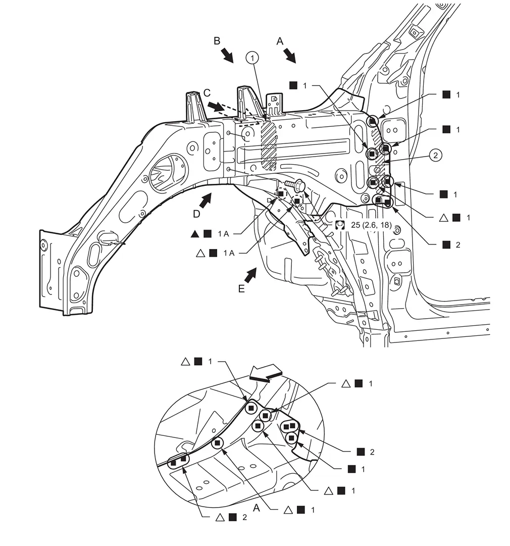
 |
Urethane foam |  |
Body sealing | ||
|
: vehicle front : Drill φ6 mm (0.24 in) hole for the plug welding hole (ultra high strength steel).
 : N•m (kg-m, ft-lb) : N•m (kg-m, ft-lb) |
|||||
| Replacement part | |||||
| • | Hoodledge assembly | • | Hoodledge reinforcement | ||
|
Urethane foam | ||||
|
: vehicle front : Drill φ6 mm (0.24 in) hole for the plug welding hole (ultra high strength steel).
: Weld the parts onto the back of the component part. |
|||||
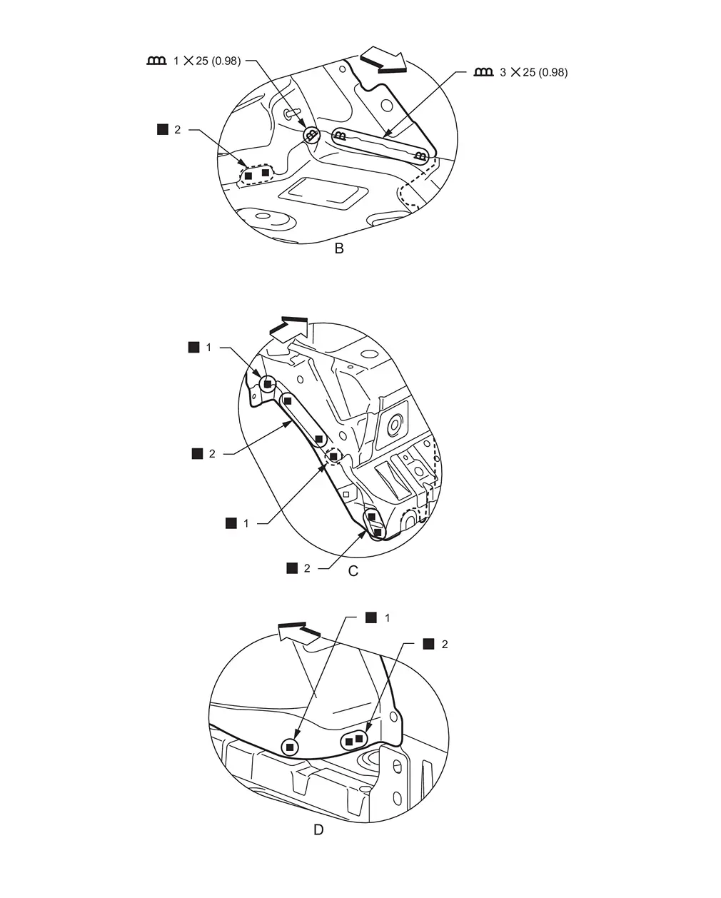
PARTIAL REPLACEMENT
Work after side radiator core support is removed.
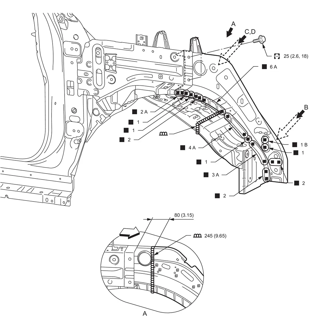
| Unit: mm (in) | |||||
|
: vehicle front : N•m (kg-m, ft-lb) |
|||||
| Replacement part | |||||
| • | Hoodledge assembly | ||||
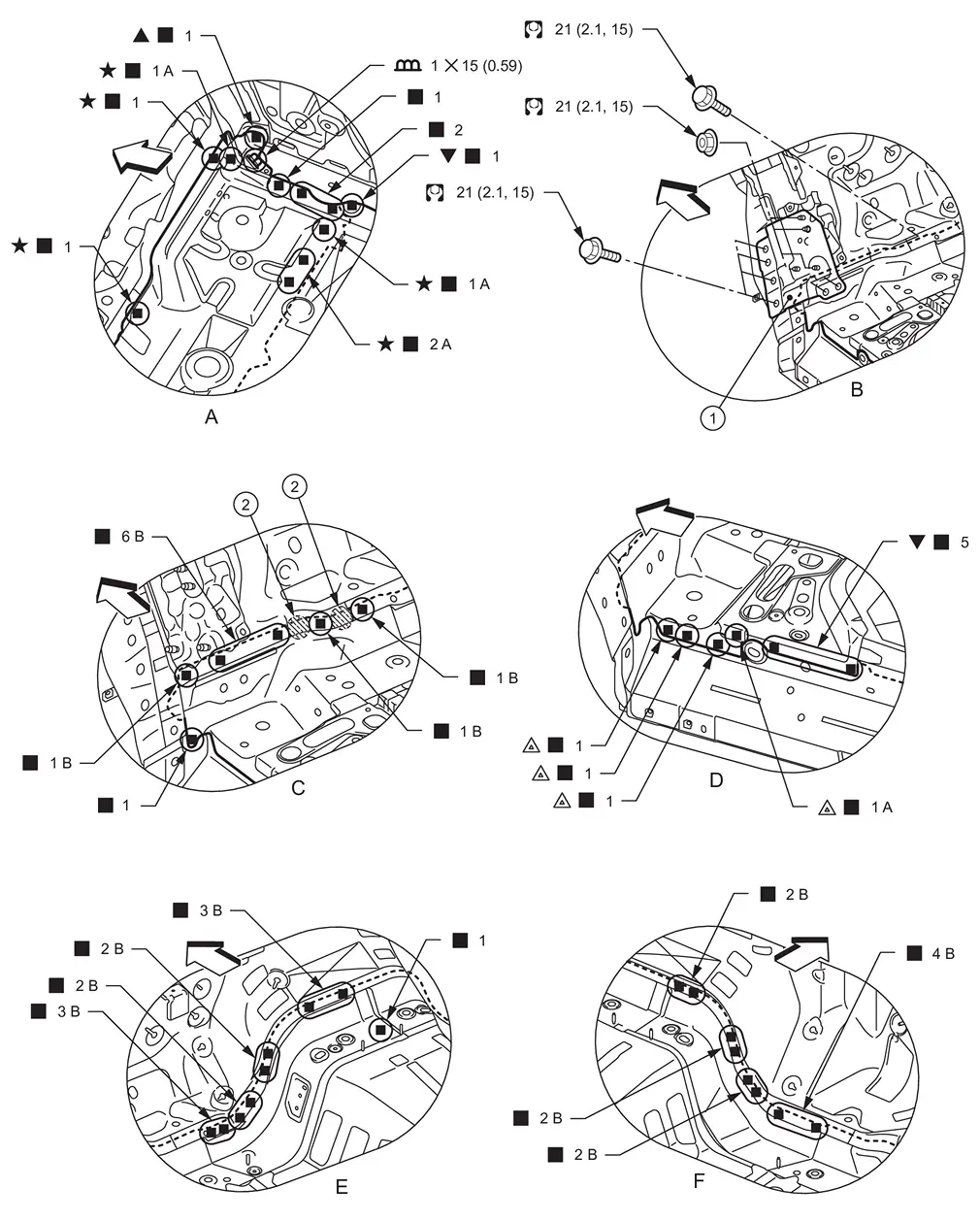
View A: Before installing hoodledge connecter bracket assembly
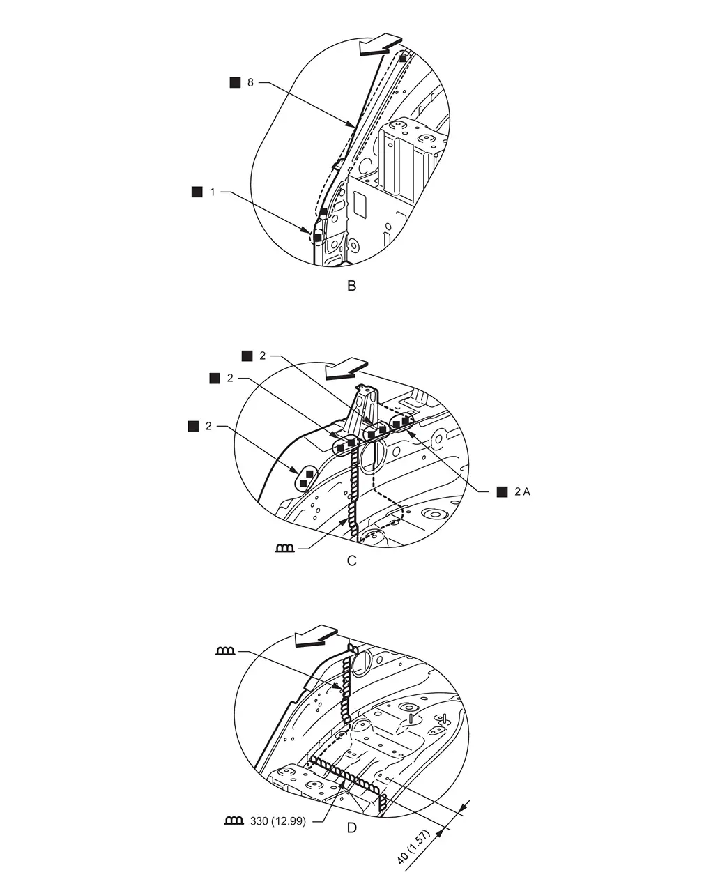
| Unit: mm (in) | |||||
|
: vehicle front : Weld the parts onto the back of the component part. |
|||||
View D: Before installing hoodledge connecter bracket assembly
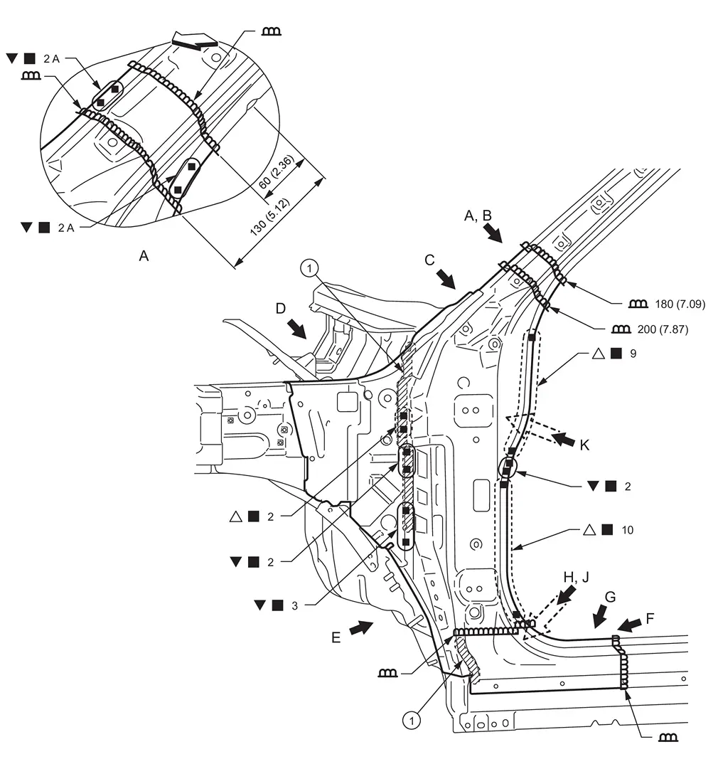
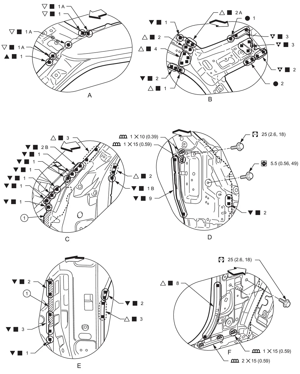
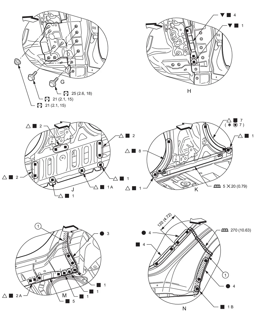
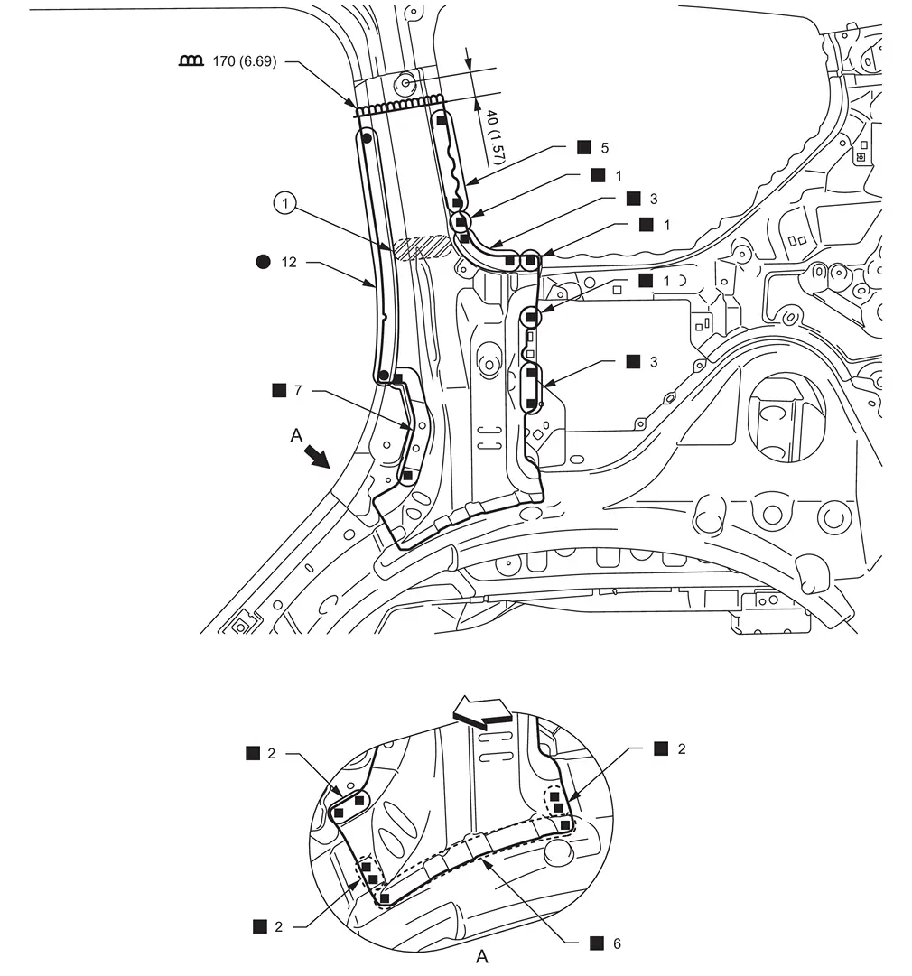
Front Pillar
WARNING:
-
Jacking up or lift up the vehicle may the vehicle height to go down which cause a personal injury and/or damage to the air suspension component parts. Refer to Precaution for when Jacking and Lifting Up the vehicle with Electronic Air Suspension System.
Work after hoodledge reinforcement and roof are removed.
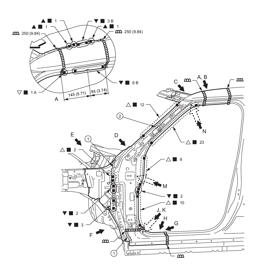
|
Body sealing | |
Urethane foam | ||
| Unit: mm (in) | |||||
|
: vehicle front : Drill φ6 mm (0.24 in) hole for the plug welding hole (ultra high strength steel).
: Weld the parts onto the back of the component part. |
|||||
| Replacement part | |||||
| • | Side body assembly | • | Side dash | • | Upper inner front pillar |
| • | Lower side dash assembly | ||||
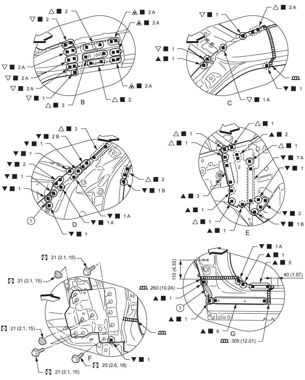
|
Body sealing | ||||
| Unit: mm (in) | |||||
|
: vehicle front : Drill φ6 mm (0.24 in) hole for the plug welding hole (ultra high strength steel).
: N•m (kg-m, ft-lb) |
|||||
 : Drill φ12 mm (0.47 in) hole for the plug welding hole (ultra high strength steel).
View B: Before installing outer front side body
View E: Before installing outer front side body and front pillar brace
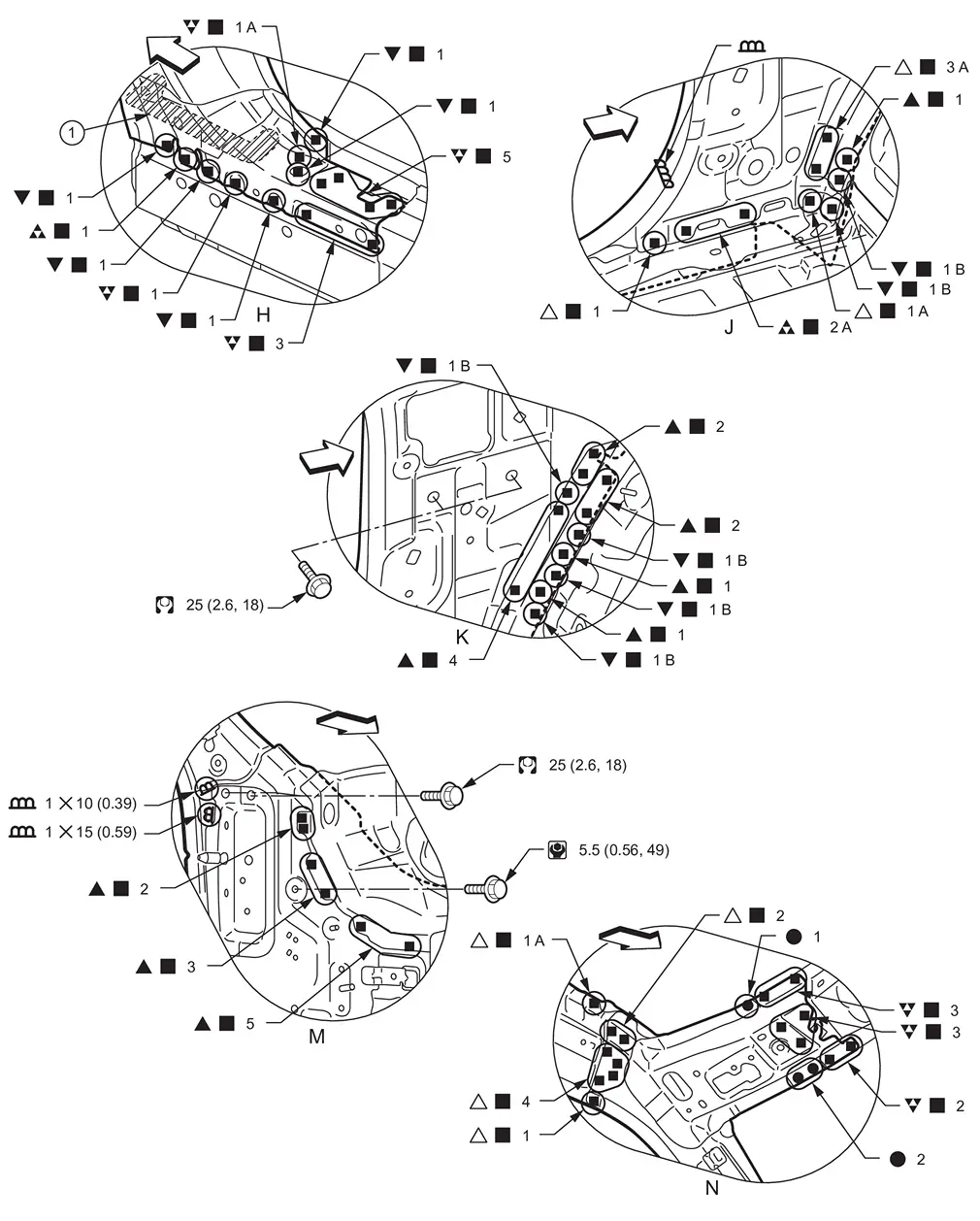
|
Urethane foam | ||||
| Unit: mm (in) | |||||
|
: vehicle front : Drill φ6 mm (0.24 in) hole for the plug welding hole (ultra high strength steel).
 : N•m (kg-m, in-lb) : N•m (kg-m, in-lb) |
|||||
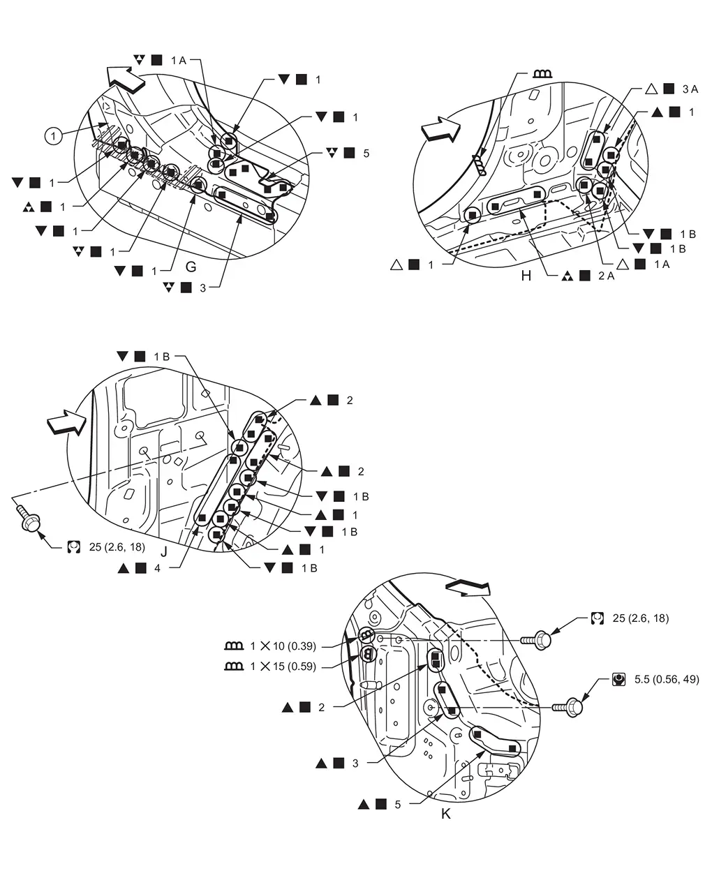
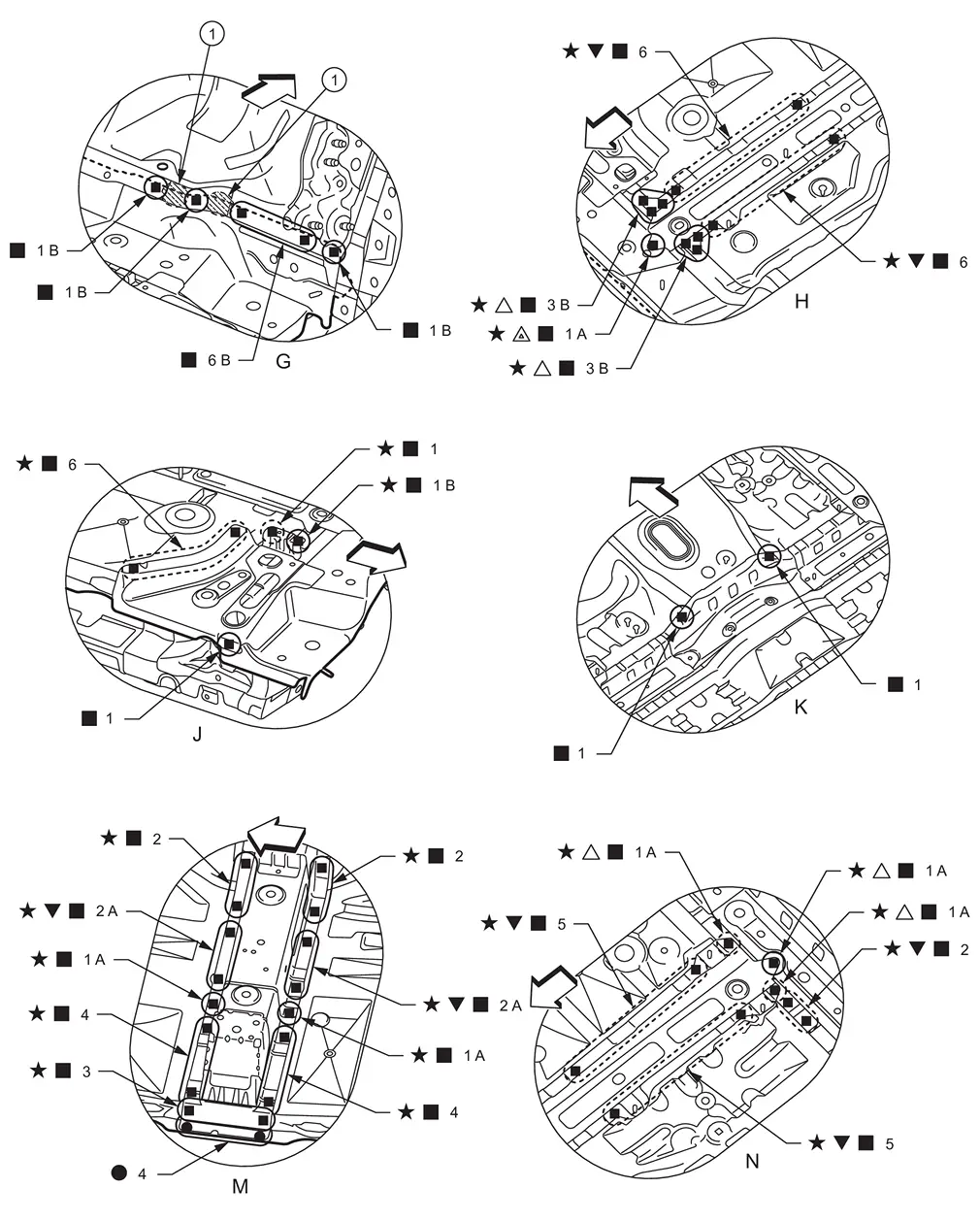
View H: Before installing outer front side body
PARTIAL REPLACEMENT
Work after hoodledge reinforcement is removed.
|
Body sealing | ||||
| Unit: mm (in) | |||||
|
: vehicle front
: Weld the parts onto the back of the component part. |
|||||
| Replacement part | |||||
| • | Side body assembly | • | Side dash | • | Lower side dash assembly |
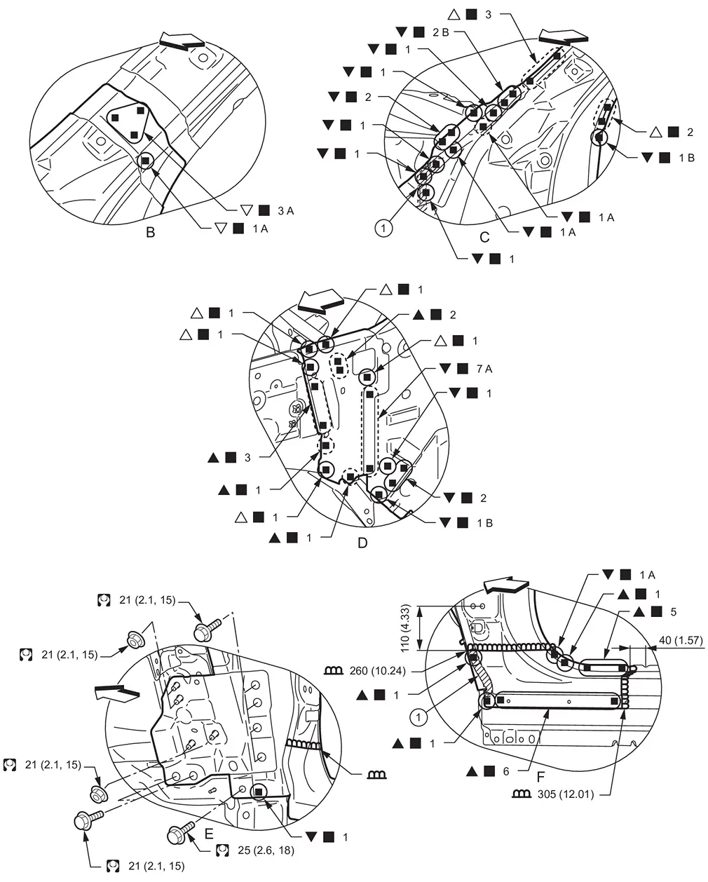
|
Body sealing | ||||
| Unit: mm (in) | |||||
|
: vehicle front : Drill φ6 mm (0.24 in) hole for the plug welding hole (ultra high strength steel).
: N•m (kg-m, ft-lb) |
|||||
View B: Before installing outer front side body
View D: Before installing outer front side body and front pillar brace
|
Body sealing | ||||
| Unit: mm (in) | |||||
|
: vehicle front : Drill φ6 mm (0.24 in) hole for the plug welding hole (ultra high strength steel).
: N•m (kg-m, in-lb) |
|||||
View G: Before installing outer front side body
Upper Dash
WARNING:
-
Jacking up or lift up the vehicle may the vehicle height to go down which cause a personal injury and/or damage to the air suspension component parts. Refer to Precaution for when Jacking and Lifting Up the vehicle with Electronic Air Suspension System.
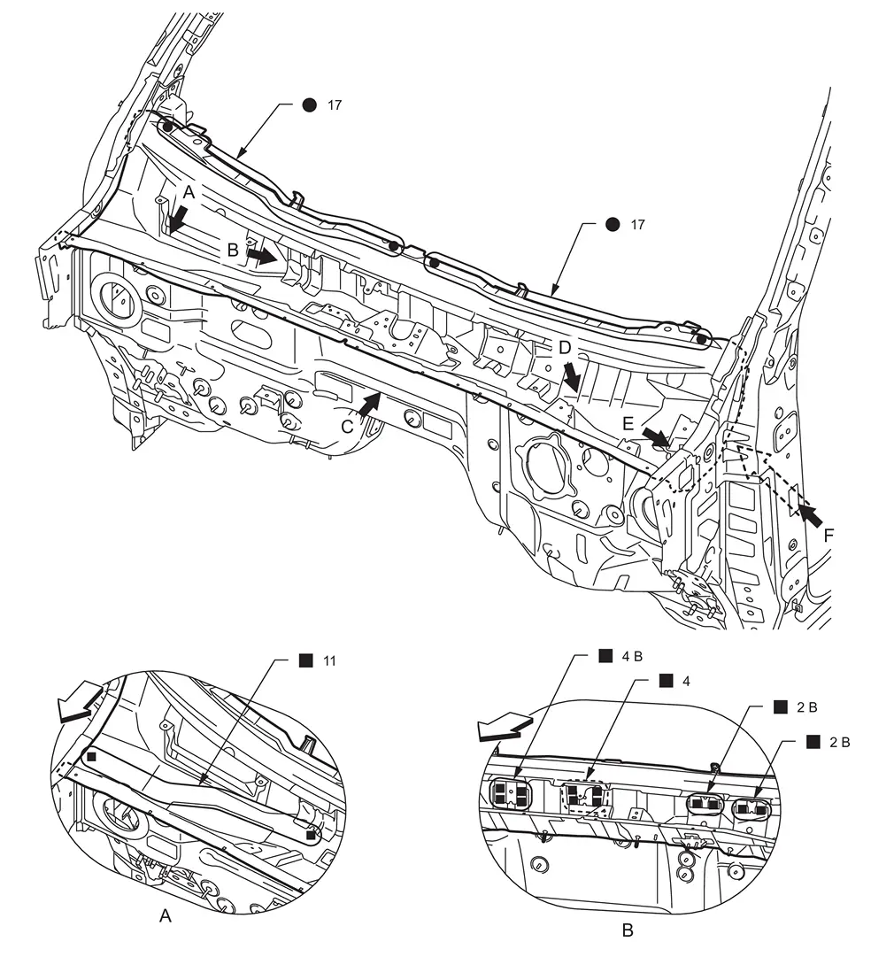
Work after radiator core main support, side radiator core support, and hoodledge are removed.
|
: vehicle front : Weld the parts onto the back of the component part. |
|||||
| Replacement part | |||||
| • | Upper dash assembly | • | Cowl top assembly | ||
|
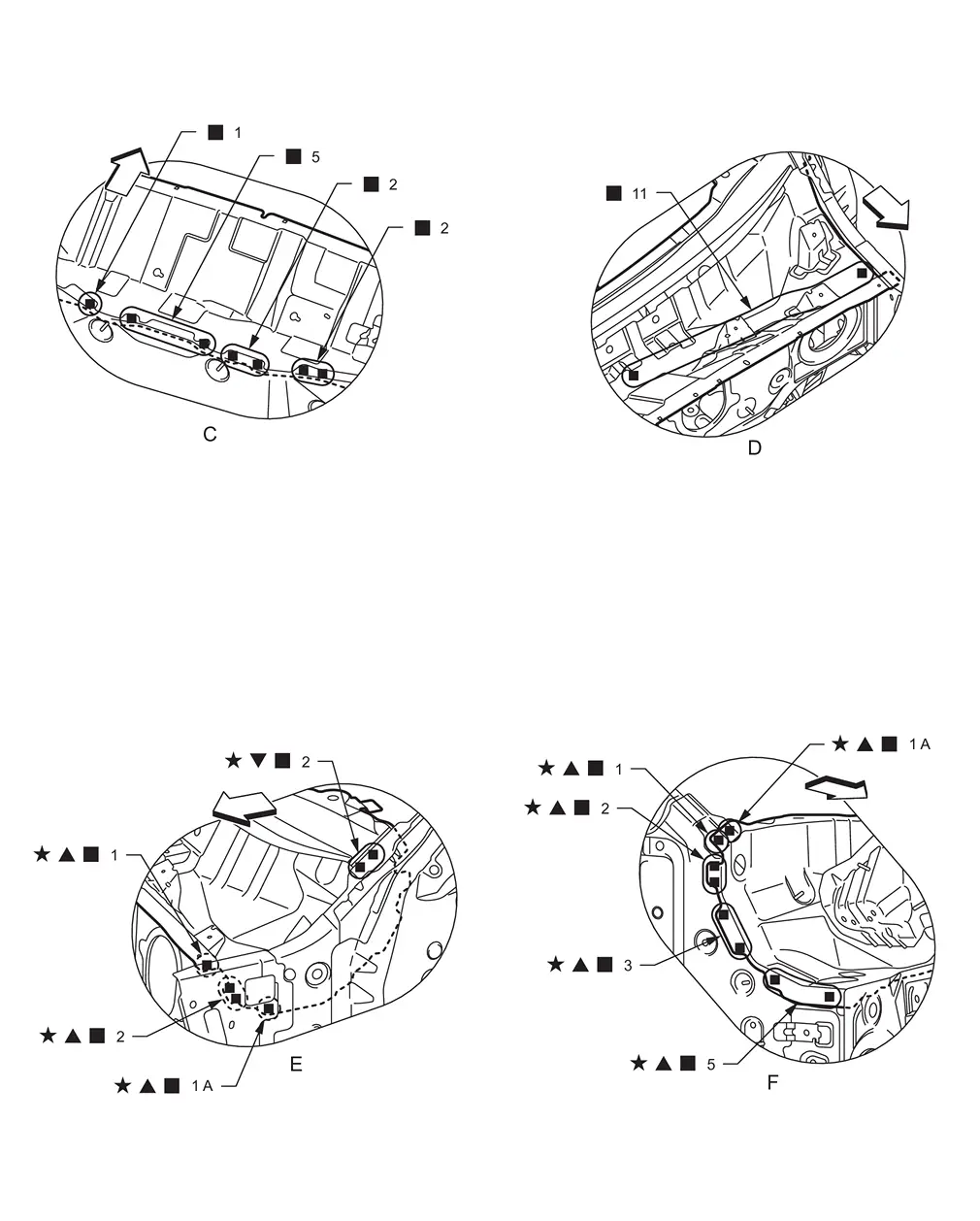
: vehicle front : Drill φ6 mm (0.24 in) hole for the plug welding hole (ultra high strength steel).
 : Welding method and the number of welding points apply to both sides of the vehicle. : Welding method and the number of welding points apply to both sides of the vehicle. |
Lower Dash
WARNING:
-
Jacking up or lift up the vehicle may the vehicle height to go down which cause a personal injury and/or damage to the air suspension component parts. Refer to Precaution for when Jacking and Lifting Up the vehicle with Electronic Air Suspension System.
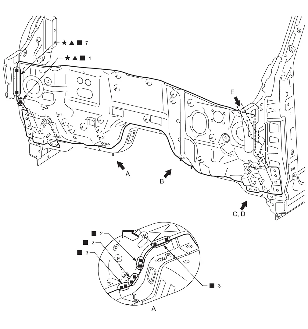
Work after radiator core main support, side radiator core support, hoodledge, and upper dash are removed.
|
: vehicle front : Drill φ6 mm (0.24 in) hole for the plug welding hole (ultra high strength steel). : Welding method and the number of welding points apply to both sides of the vehicle. |
|||||
| Replacement part | |||||
| • | Lower dash complete | • | Lower side dash assembly | ||
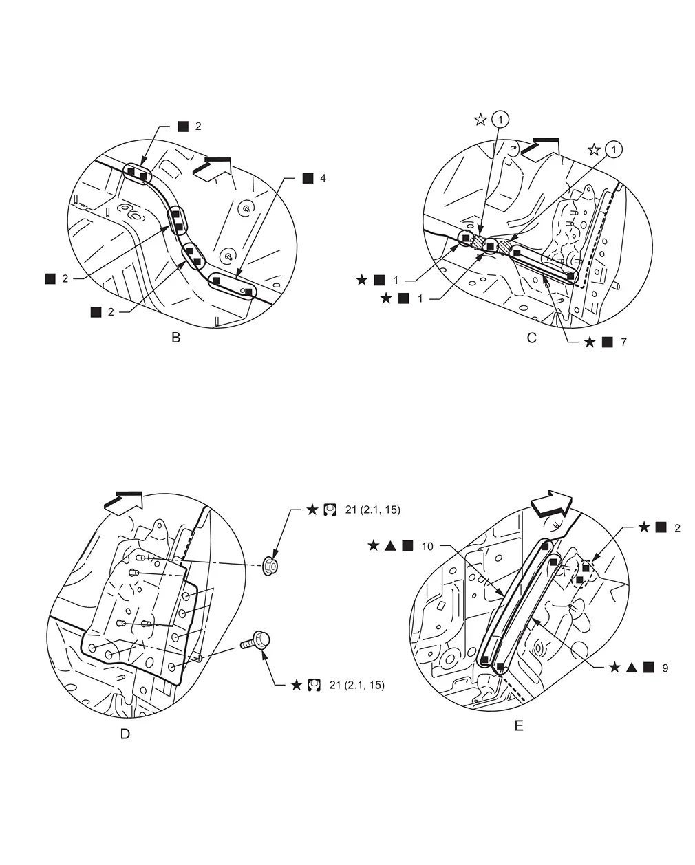
|
Adhesive | ||||
|
: vehicle front : Drill φ6 mm (0.24 in) hole for the plug welding hole (ultra high strength steel).
 : Adhesive portion apply to both sides of the vehicle. : Adhesive portion apply to both sides of the vehicle. |
|||||
View C: Before installing lower side dash assembly
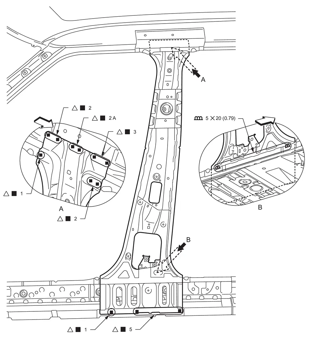
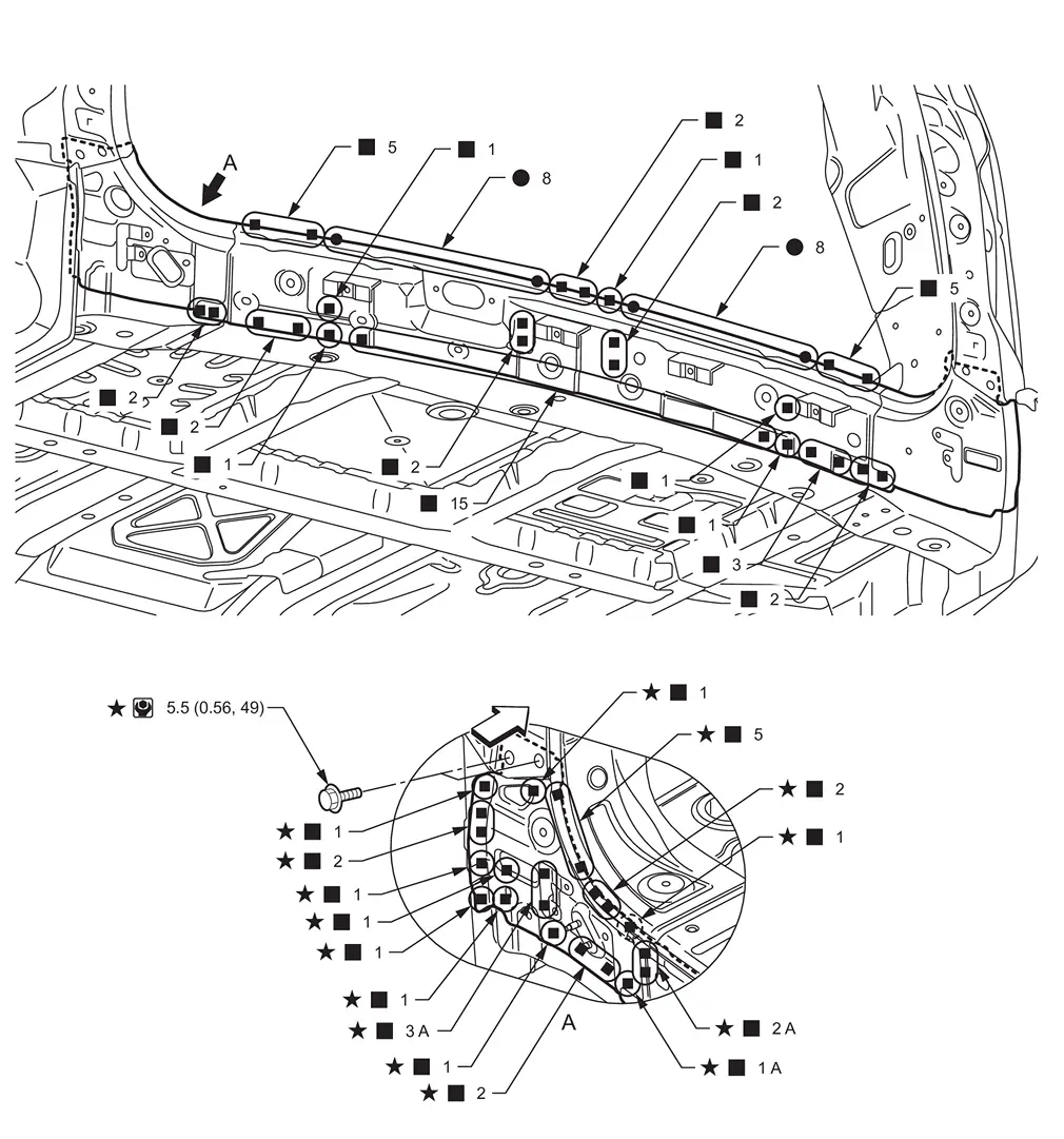
Center Pillar
WARNING:
-
Jacking up or lift up the vehicle may the vehicle height to go down which cause a personal injury and/or damage to the air suspension component parts. Refer to Precaution for when Jacking and Lifting Up the vehicle with Electronic Air Suspension System.
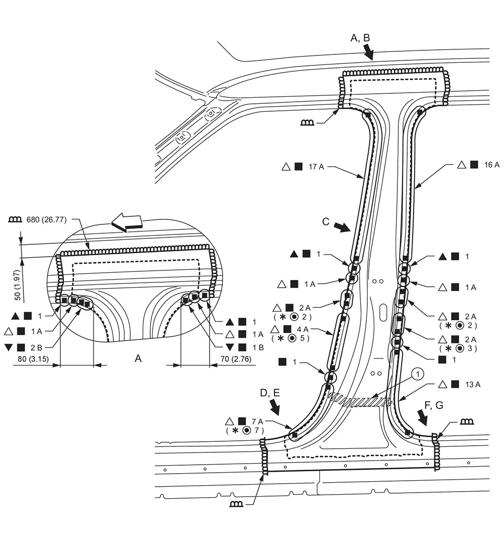
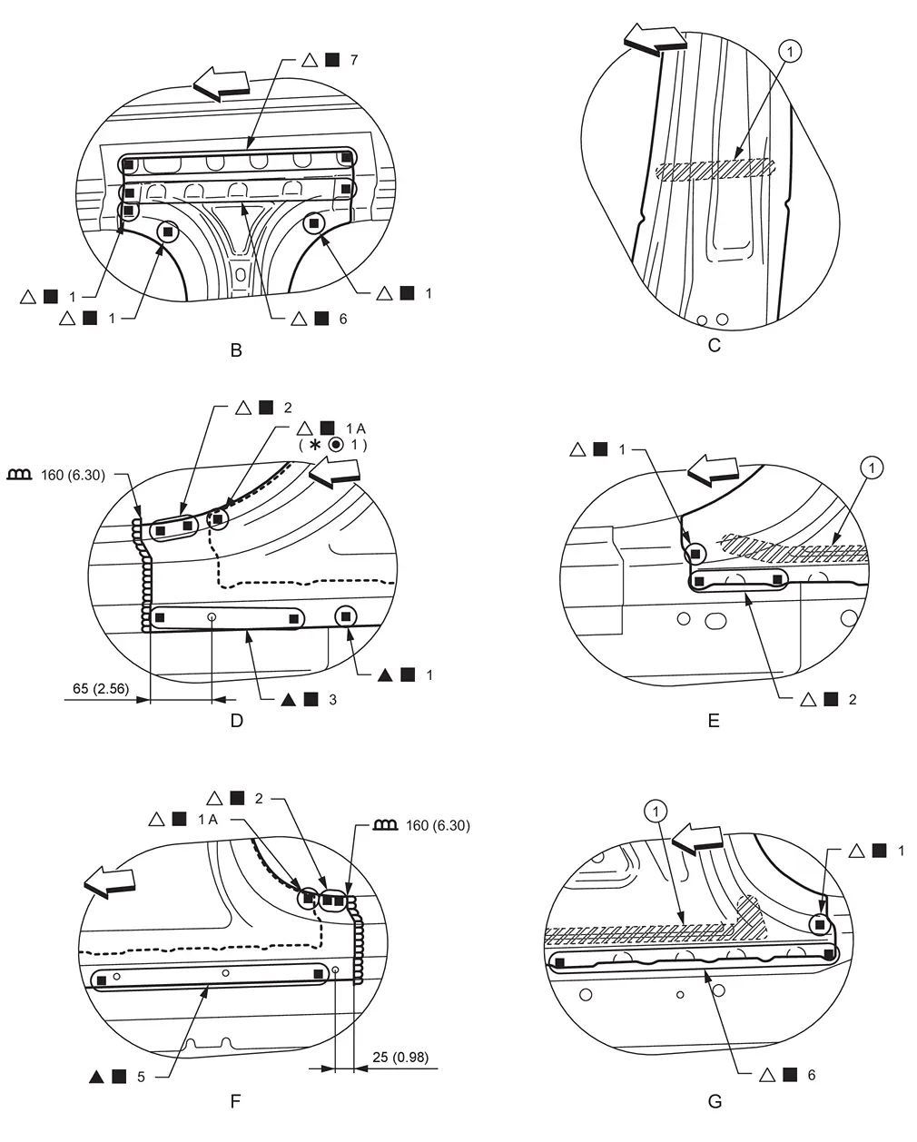
|
Urethane foam | ||||
| Unit: mm (in) | |||||
|
: vehicle front : Drill φ6 mm (0.24 in) hole for the plug welding hole (ultra high strength steel).
|
|||||
| Replacement part | |||||
| • | Outer front side body | • | Lower center pillar brace | ||
|
Urethane foam | ||||
| Unit: mm (in) | |||||
|
: vehicle front : Drill φ6 mm (0.24 in) hole for the plug welding hole (ultra high strength steel).
|
|||||
View B, C, E, and G: Before installing outer front side body
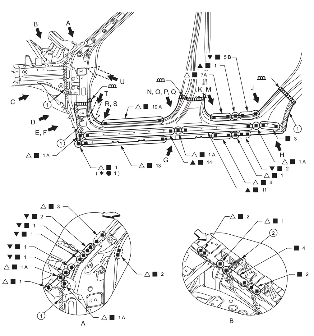
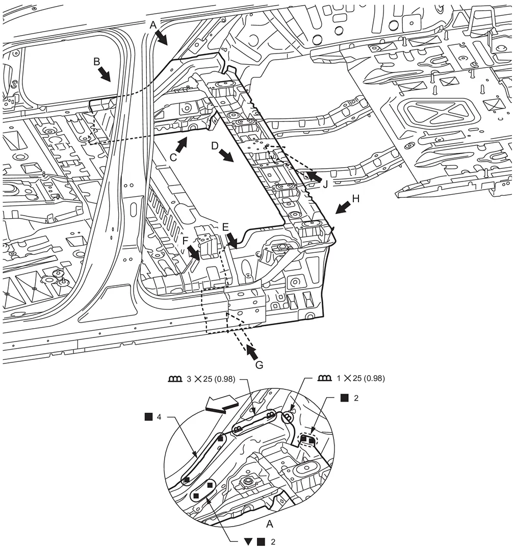
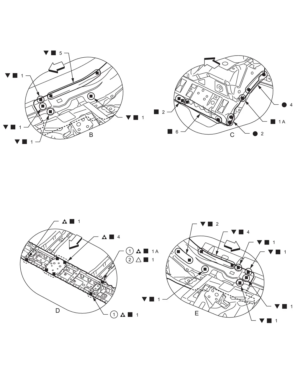
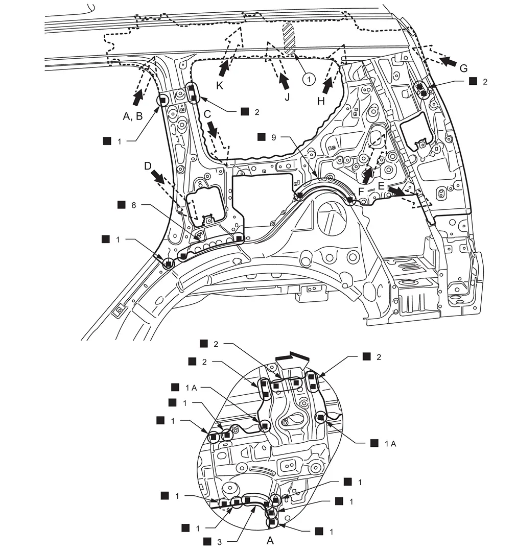
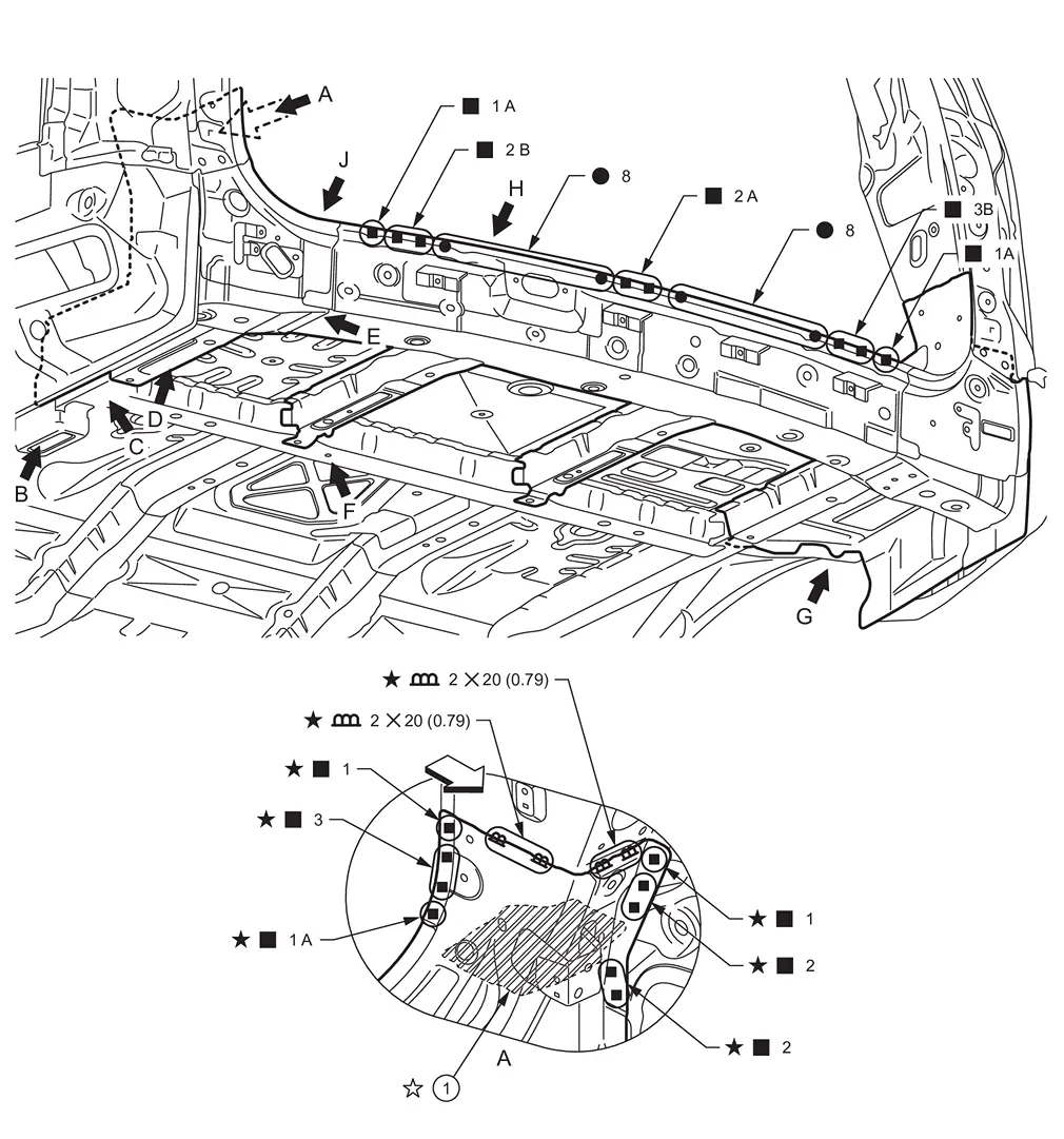
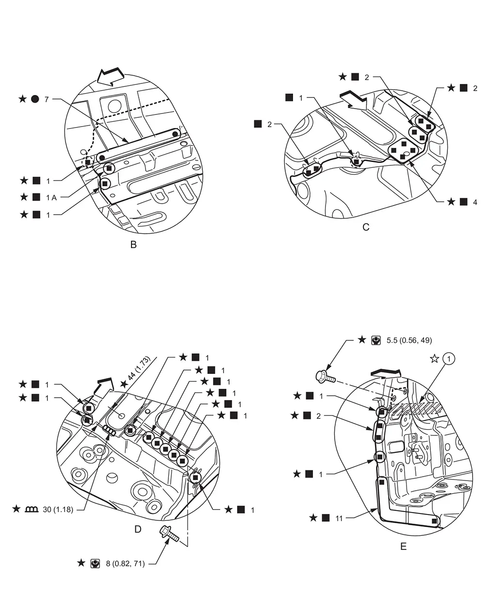
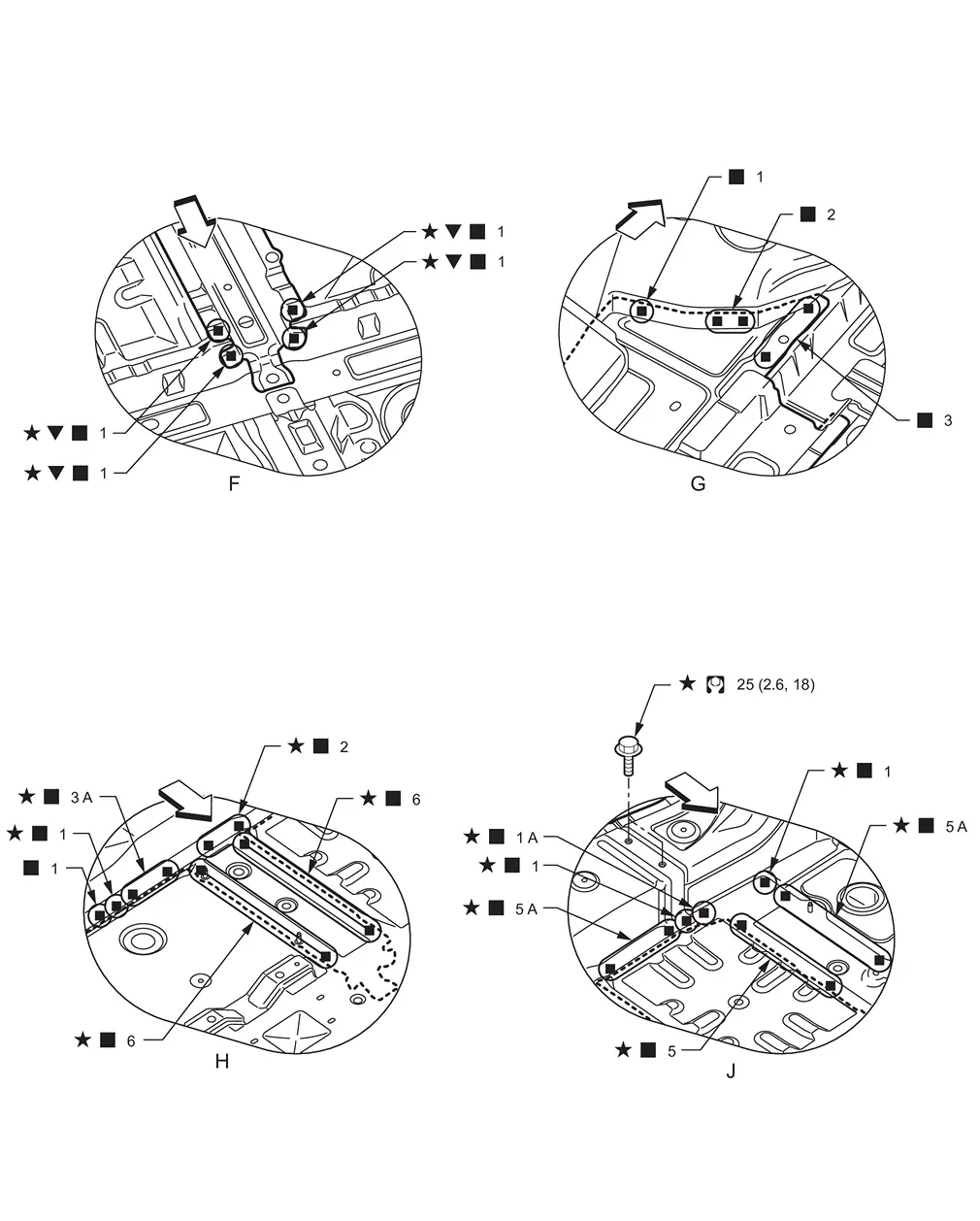
Side Body
WARNING:
-
Jacking up or lift up the vehicle may the vehicle height to go down which cause a personal injury and/or damage to the air suspension component parts. Refer to Precaution for when Jacking and Lifting Up the vehicle with Electronic Air Suspension System.
Work after hoodledge reinforcement and roof are removed.
Remove the lower side dash assembly (reusable) from the vehicle for easier installation.
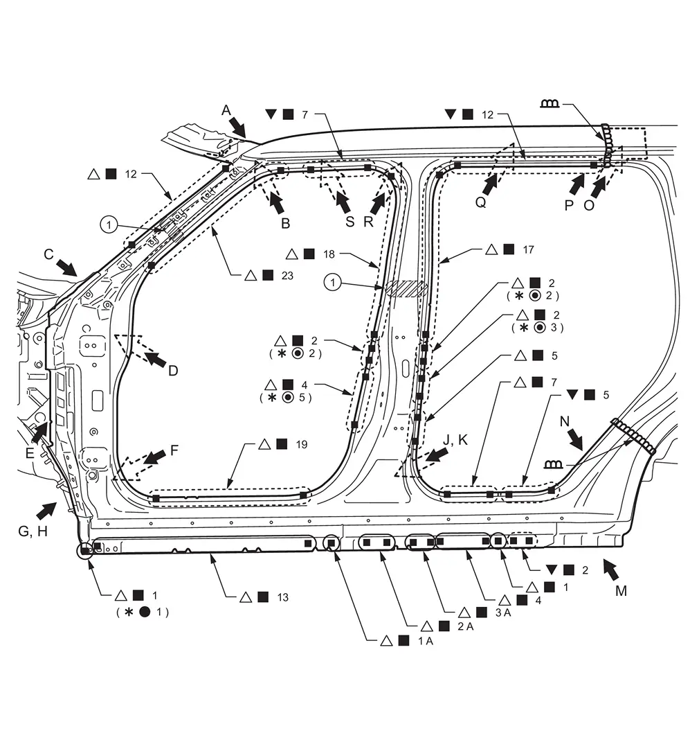
|
Urethane foam | ||||
|
|
|||||
| Replacement part | |||||
| • | Upper inner front pillar | • | Inner side roof rail | • | Inner center pillar |
| • | Side body assembly | • | Lower side dash assembly | ||
|
Body sealing | ||||
| Unit: mm (in) | |||||
|
: vehicle front : Drill φ6 mm (0.24 in) hole for the plug welding hole (ultra high strength steel).
: N•m (kg-m, in-lb) |
|||||
|
Body sealing | ||||
| Unit: mm (in) | |||||
|
: vehicle front
*: For spot welding of steel plate of tensile strength 980 MPa, observe the indicated welding conditions. Refer to Welding of Ultra High Strength Steel. : N•m (kg-m, ft-lb) |
|||||
View H: Before installing lower side dash assembly
View J: Inner center pillar (replacement part) and side body assembly (replacement part)
|
Urethane foam | ||||
| Unit: mm (in) | |||||
|
: vehicle front : Drill φ6 mm (0.24 in) hole for the plug welding hole (ultra high strength steel).
: N•m (kg-m, in-lb) |
|||||
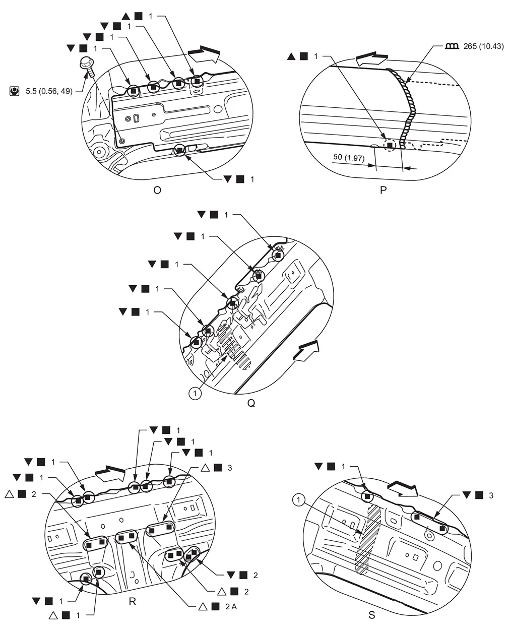
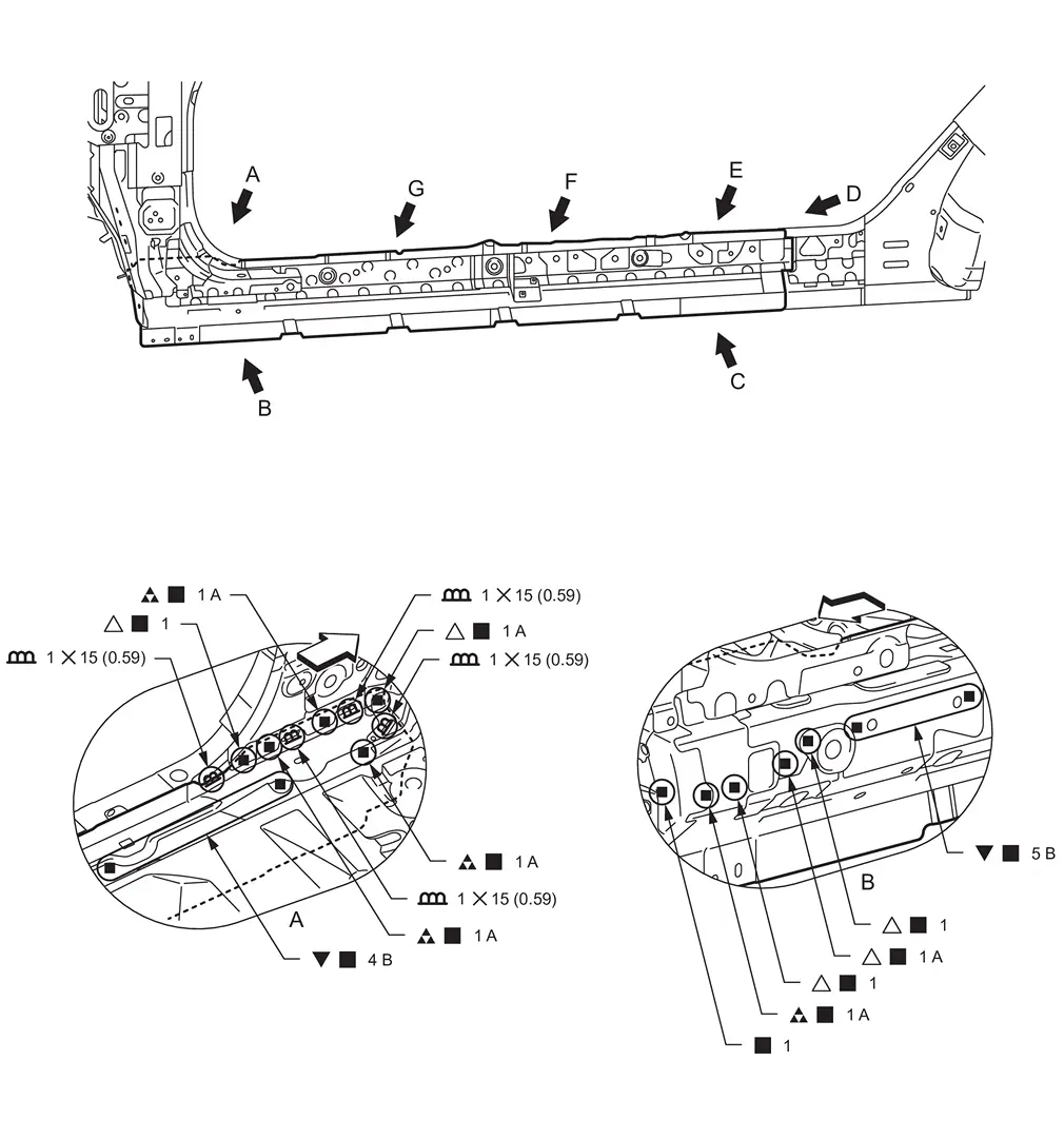
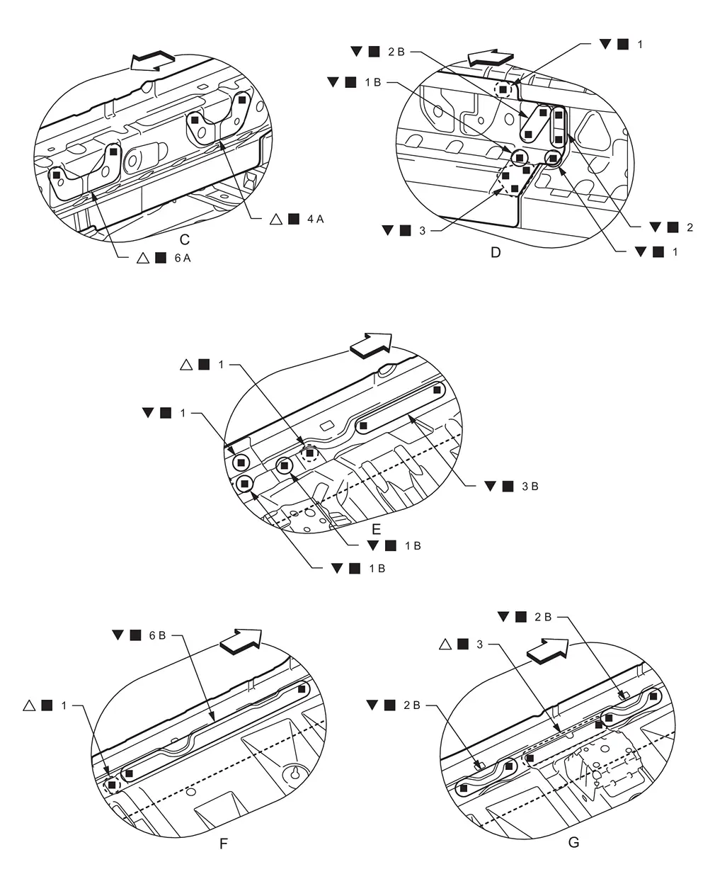
Outer Sill
WARNING:
-
Jacking up or lift up the vehicle may the vehicle height to go down which cause a personal injury and/or damage to the air suspension component parts. Refer to Precaution for when Jacking and Lifting Up the vehicle with Electronic Air Suspension System.
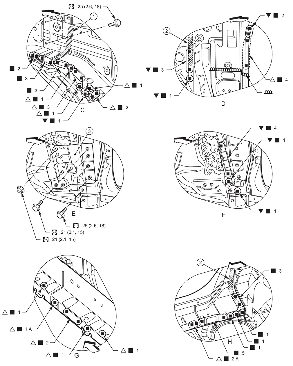
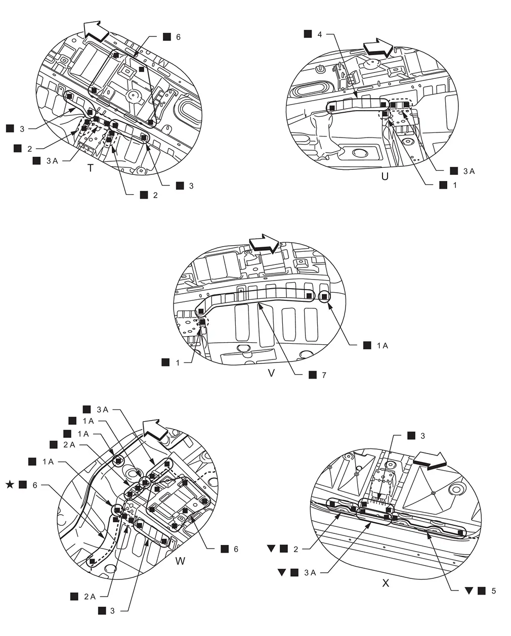
For easier installation, remove the "View A, B, C, D, E, F and U" weld point, bolt and nut.
Remove the lower side dash assembly (reusable) from the vehicle for easier installation.
|
Body sealing |  |
Urethane foam | ||
|
: vehicle front : Drill φ6 mm (0.24 in) hole for the plug welding hole (ultra high strength steel).
|
|||||
| Replacement part | |||||
| • | Outer sill assembly | • | Outer sill reinforcement | ||
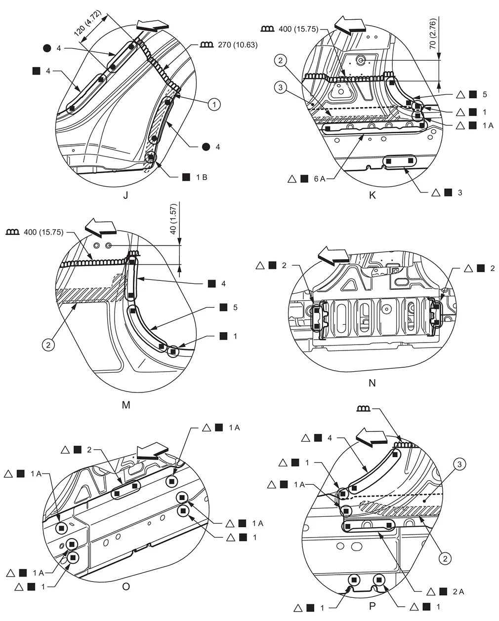
|
Urethane foam | |
Body sealing |  |
Lower side dash assembly (reusable) |
|
: vehicle front
: N•m (kg-m, ft-lb) |
|||||
View F: Before installing lower side dash assembly
View G: Before installing outer sill assembly
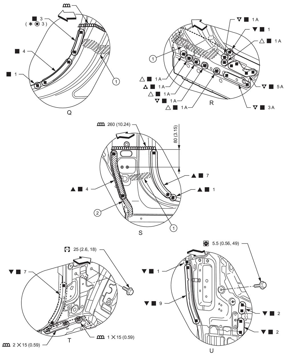
|
Body sealing | |
Urethane foam | |
Lower center pillar brace (reusable) |
| Unit: mm (in) | |||||
|
: vehicle front  : Drill φ8 mm (0.31 in) hole for the plug welding hole (ultra high strength steel). : Drill φ8 mm (0.31 in) hole for the plug welding hole (ultra high strength steel). |
|||||
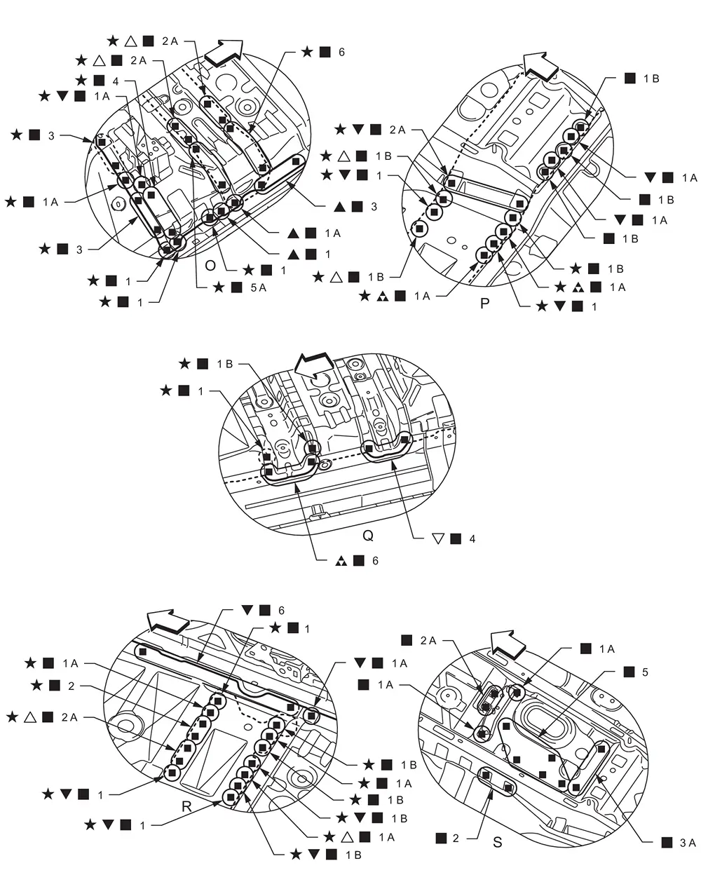
View K and P: Before installing outer sill assembly
View N: Before installing outer sill assembly, lower center pillar brace, and outer sill reinforcement
View O: Before installing outer sill assembly and lower center pillar brace
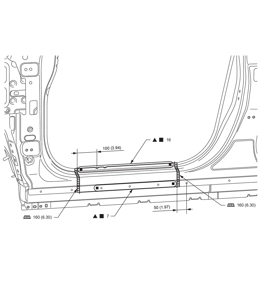
|
Urethane foam | |
Body sealing | ||
| Unit: mm (in) | |||||
|
: vehicle front : Drill φ6 mm (0.24 in) hole for the plug welding hole (ultra high strength steel).
*: For spot welding of steel plate of tensile strength 980 MPa, observe the indicated welding conditions. Refer to Welding of Ultra High Strength Steel.
: N•m (kg-m, in-lb) |
|||||
View R and T: Before installing outer sill assembly
PARTIAL REPLACEMENT
| Unit: mm (in) | |||||
| : Drill φ6 mm (0.24 in) hole for the plug welding hole (ultra high strength steel). | |||||
| Replacement part | |||||
| • | Outer sill assembly | ||||
Inner Center Pillar
WARNING:
-
Jacking up or lift up the vehicle may the vehicle height to go down which cause a personal injury and/or damage to the air suspension component parts. Refer to Precaution for when Jacking and Lifting Up the vehicle with Electronic Air Suspension System.
Work after center pillar and outer sill are removed.
| Unit: mm (in) | |||||
| : vehicle front | |||||
| : Drill φ8 mm (0.31 in) hole for the plug welding hole (ultra high strength steel). |
|||||
| Replacement part | |||||
| • | Inner center pillar | ||||
Inner Sill
WARNING:
-
Jacking up or lift up the vehicle may the vehicle height to go down which cause a personal injury and/or damage to the air suspension component parts. Refer to Precaution for when Jacking and Lifting Up the vehicle with Electronic Air Suspension System.
Work after lower side dash assembly, center pillar, outer sill, and inner center pillar are removed.
| Unit: mm (in) | |||||
| : vehicle front | |||||
 : Drill φ7 mm (0.28 in) hole for the plug welding hole (ultra high strength steel). : Drill φ7 mm (0.28 in) hole for the plug welding hole (ultra high strength steel). |
|||||
| : Drill φ8 mm (0.31 in) hole for the plug welding hole (ultra high strength steel). |
|||||
 : Drill φ10 mm (0.39 in) hole for the plug welding hole (ultra high strength steel). : Drill φ10 mm (0.39 in) hole for the plug welding hole (ultra high strength steel). |
|||||
| Replacement part | |||||
| • | Inner sill | ||||
| : vehicle front | |||||
| : Drill φ7 mm (0.28 in) hole for the plug welding hole (ultra high strength steel). |
|||||
| : Drill φ8 mm (0.31 in) hole for the plug welding hole (ultra high strength steel). |
|||||
| : Weld the parts onto the back of the component part. |
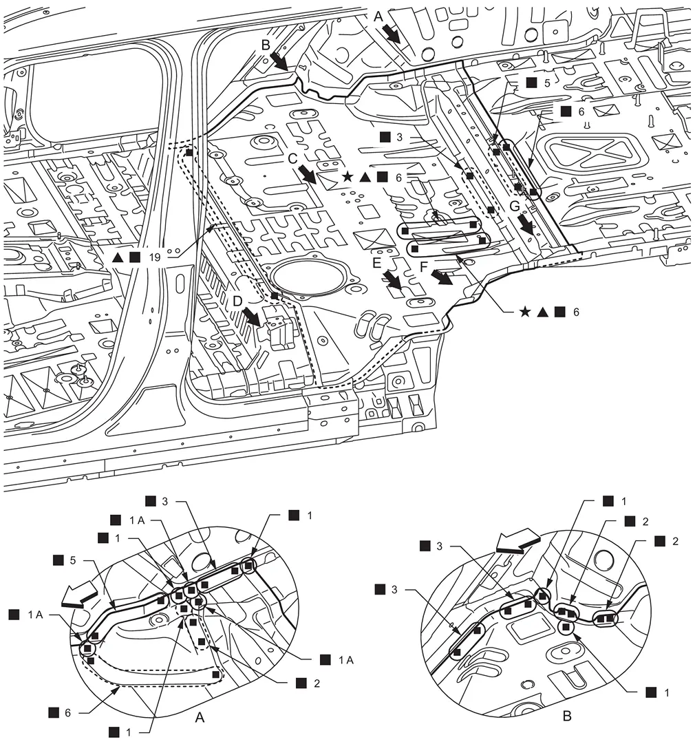
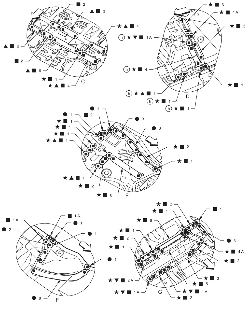
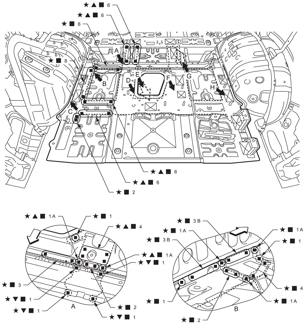
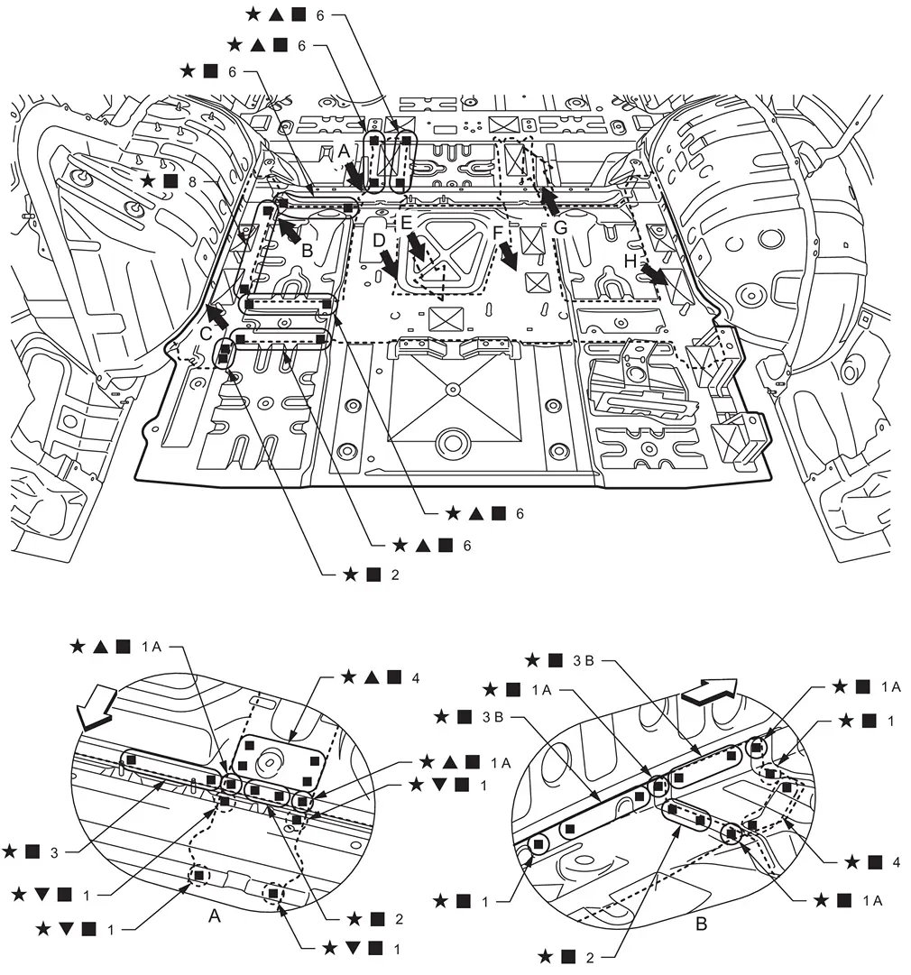
Front Floor
WARNING:
-
Jacking up or lift up the vehicle may the vehicle height to go down which cause a personal injury and/or damage to the air suspension component parts. Refer to Precaution for when Jacking and Lifting Up the vehicle with Electronic Air Suspension System.
Work after lower side dash assembly (LH), outer sill, and inner sill (LH) are removed.
Remove the lower side dash assembly (RH, reusable) from the vehicle for easier installation.
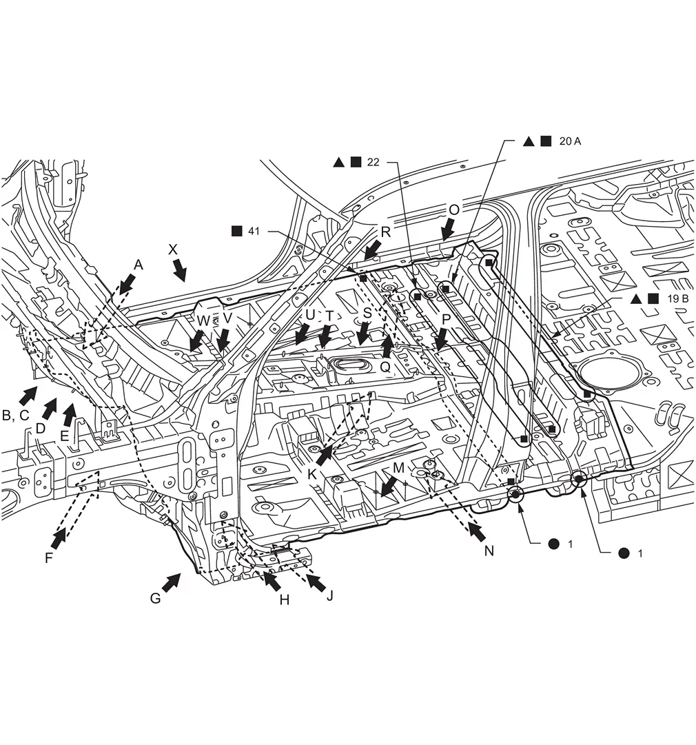
| : Drill φ6 mm (0.24 in) hole for the plug welding hole (ultra high strength steel). | |||||
| : Weld the parts onto the back of the component part. |
|||||
| Replacement part | |||||
| • | Front floor assembly | • | 2nd crossmember assembly (RH & LH) | • | Front floor reinforcement assembly |
| • | Rear floor front extension | • | Front side member assembly (RH & LH) | • | Front seat mounting rear crossmember assembly |
| • | 4th crossmember assembly | ||||
|
Lower side dash assembly (RH, reusable) | |
Adhesive | ||
| Unit: mm (in) | |||||
| : vehicle front | |||||
| : Drill φ6 mm (0.24 in) hole for the plug welding hole (ultra high strength steel). | |||||
| : Drill φ7 mm (0.28 in) hole for the plug welding hole (ultra high strength steel). |
|||||
 : Drill φ14 mm (0.55 in) hole for the plug welding hole (ultra high strength steel). : Drill φ14 mm (0.55 in) hole for the plug welding hole (ultra high strength steel). |
|||||
| : Welding method and the number of welding points apply to both sides of the vehicle. |
|||||
| : N•m (kg-m, ft-lb) |
|||||
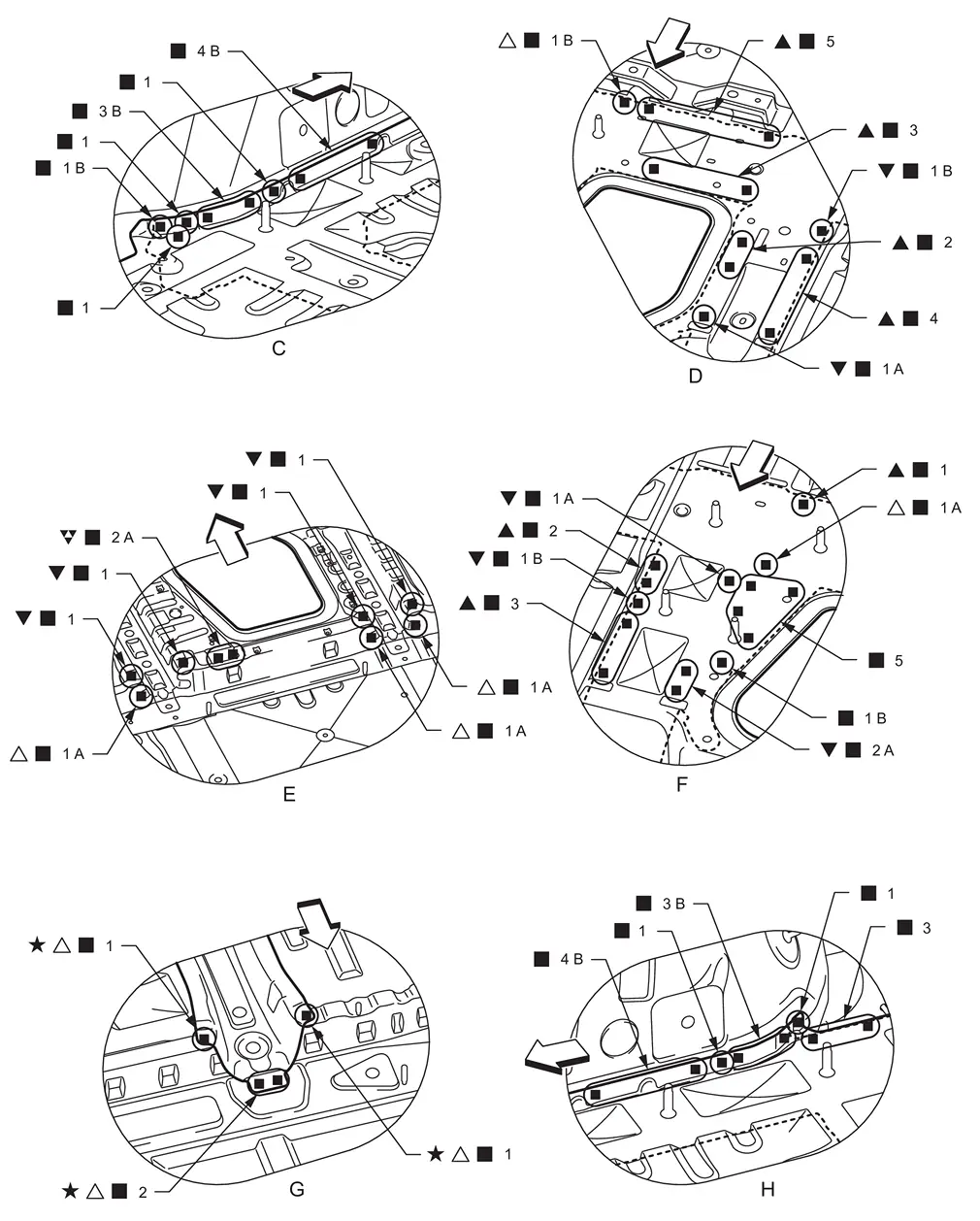
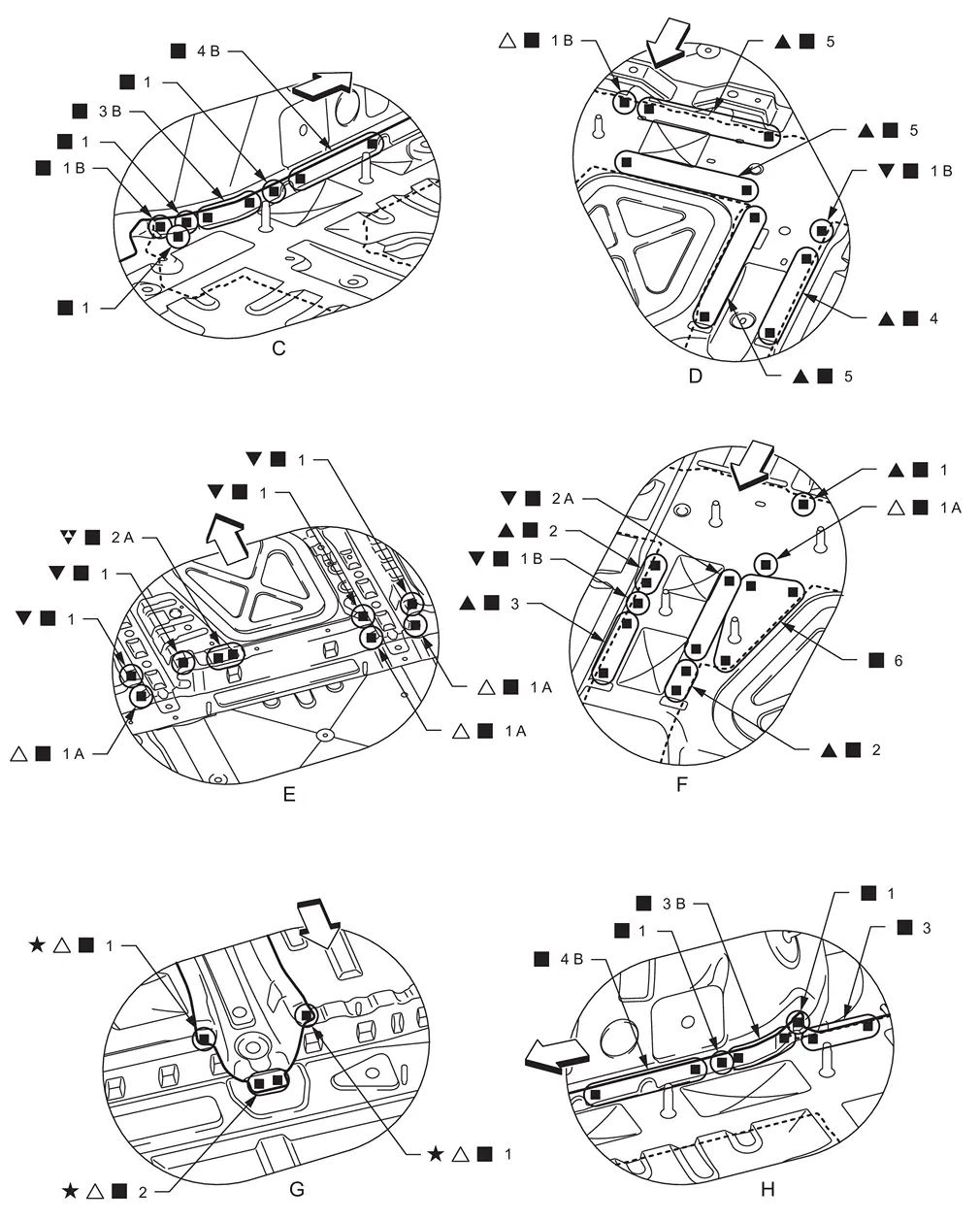
View C and D: Before installing lower side dash assembly
|
Adhesive | ||||
| : vehicle front | |||||
| : Drill φ7 mm (0.28 in) hole for the plug welding hole (ultra high strength steel). |
|||||
| : Drill φ8 mm (0.31 in) hole for the plug welding hole (ultra high strength steel). |
|||||
| : Drill φ14 mm (0.55 in) hole for the plug welding hole (ultra high strength steel). |
|||||
| : Weld the parts onto the back of the component part. |
|||||
| : Welding method and the number of welding points apply to both sides of the vehicle. |
|||||
| : vehicle front | |||||
| : Drill φ6 mm (0.24 in) hole for the plug welding hole (ultra high strength steel). | |||||
| : Drill φ7 mm (0.28 in) hole for the plug welding hole (ultra high strength steel). |
|||||
| : Drill φ8 mm (0.31 in) hole for the plug welding hole (ultra high strength steel). |
|||||
 : Drill φ9 mm (0.35 in) hole for the plug welding hole (ultra high strength steel). : Drill φ9 mm (0.35 in) hole for the plug welding hole (ultra high strength steel). |
|||||
| : Drill φ10 mm (0.39 in) hole for the plug welding hole (ultra high strength steel). |
|||||
| : Weld the parts onto the back of the component part. |
|||||
| : Welding method and the number of welding points apply to both sides of the vehicle. |
| : vehicle front | |||||
| : Drill φ7 mm (0.28 in) hole for the plug welding hole (ultra high strength steel). |
|||||
| : Weld the parts onto the back of the component part. |
|||||
| : Welding method and the number of welding points apply to both sides of the vehicle. |
Rear Floor Front
WARNING:
-
Jacking up or lift up the vehicle may the vehicle height to go down which cause a personal injury and/or damage to the air suspension component parts. Refer to Precaution for when Jacking and Lifting Up the vehicle with Electronic Air Suspension System.
Work after rear fender, outer rear sill reinforcement, outer rear wheelhouse, and inner rear wheelhouse are removed.
Remove the welding point  for easier installation.
| : vehicle front | |||||
| : Drill φ6 mm (0.24 in) hole for the plug welding hole (ultra high strength steel). | |||||
| : Weld the parts onto the back of the component part. |
|||||
| : Welding method and the number of welding points apply to both sides of the vehicle. |
|||||
| Replacement part | |||||
| • | Inner rear wheelhouse reinforcement assembly (RH & LH) | • | Rear floor front | • | 3rd seat mounting bracket |
| : vehicle front | |||||
| : Drill φ6 mm (0.24 in) hole for the plug welding hole (ultra high strength steel). | |||||
| : Drill φ7 mm (0.28 in) hole for the plug welding hole (ultra high strength steel). |
|||||
| : Weld the parts onto the back of the component part. |
|||||
| : Welding method and the number of welding points apply to both sides of the vehicle. |
Rear Seat Crossmember
WARNING:
-
Jacking up or lift up the vehicle may the vehicle height to go down which cause a personal injury and/or damage to the air suspension component parts. Refer to Precaution for when Jacking and Lifting Up the vehicle with Electronic Air Suspension System.
Work after rear fender, outer rear sill reinforcement, outer rear wheelhouse, inner rear wheelhouse, and rear floor front are removed.
Weld "view F" as shown in the illustration after installing the rear floor front.
| Unit: mm (in) | |||||
| : vehicle front | |||||
| : Drill φ7 mm (0.28 in) hole for the plug welding hole (ultra high strength steel). |
|||||
| : Weld the parts onto the back of the component part. |
|||||
| Replacement part | |||||
| • | Rear seat crossmember assembly | ||||
|
Captain seat | |
Bench seat | ||
| : vehicle front | |||||
| : Drill φ7 mm (0.28 in) hole for the plug welding hole (ultra high strength steel). |
|||||
| : Drill φ8 mm (0.31 in) hole for the plug welding hole (ultra high strength steel). |
|||||
| : Drill φ10 mm (0.39 in) hole for the plug welding hole (ultra high strength steel). |
|||||
| : Weld the parts onto the back of the component part. |
|||||
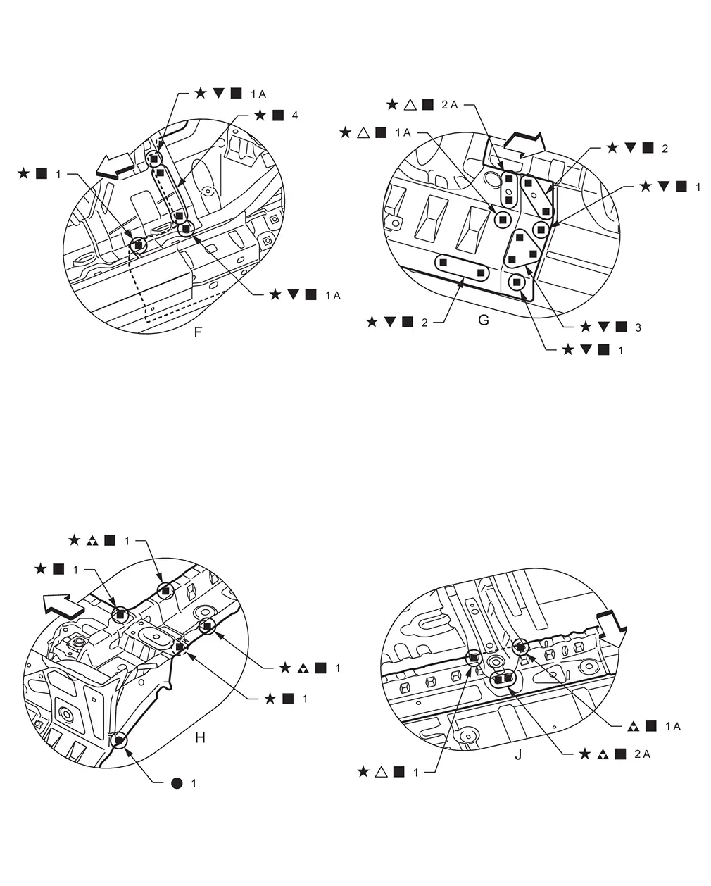
| : vehicle front | |||||
| : Drill φ7 mm (0.28 in) hole for the plug welding hole (ultra high strength steel). |
|||||
| : Drill φ8 mm (0.31 in) hole for the plug welding hole (ultra high strength steel). |
|||||
| : Drill φ10 mm (0.39 in) hole for the plug welding hole (ultra high strength steel). |
|||||
| : Weld the parts onto the back of the component part. |
|||||
| : Welding method and the number of welding points apply to both sides of the vehicle. |
Rear Fender
WARNING:
-
Jacking up or lift up the vehicle may the vehicle height to go down which cause a personal injury and/or damage to the air suspension component parts. Refer to Precaution for when Jacking and Lifting Up the vehicle with Electronic Air Suspension System.
Work after roof is removed.
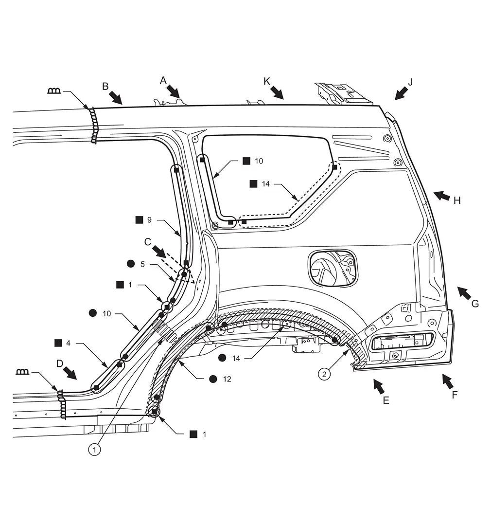
|
Urethane foam | |
Body sealing | ||
| : Weld the parts onto the back of the component part. |
|||||
| Replacement part | |||||
| • | Rear fender | ||||
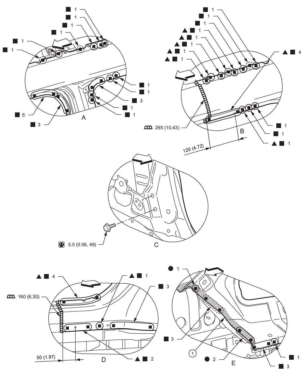
|
Body sealing | ||||
| Unit: mm (in) | |||||
| : vehicle front | |||||
| : Drill φ6 mm (0.24 in) hole for the plug welding hole (ultra high strength steel). | |||||
| : Weld the parts onto the back of the component part. |
|||||
| : N•m (kg-m, in-lb) |
|||||
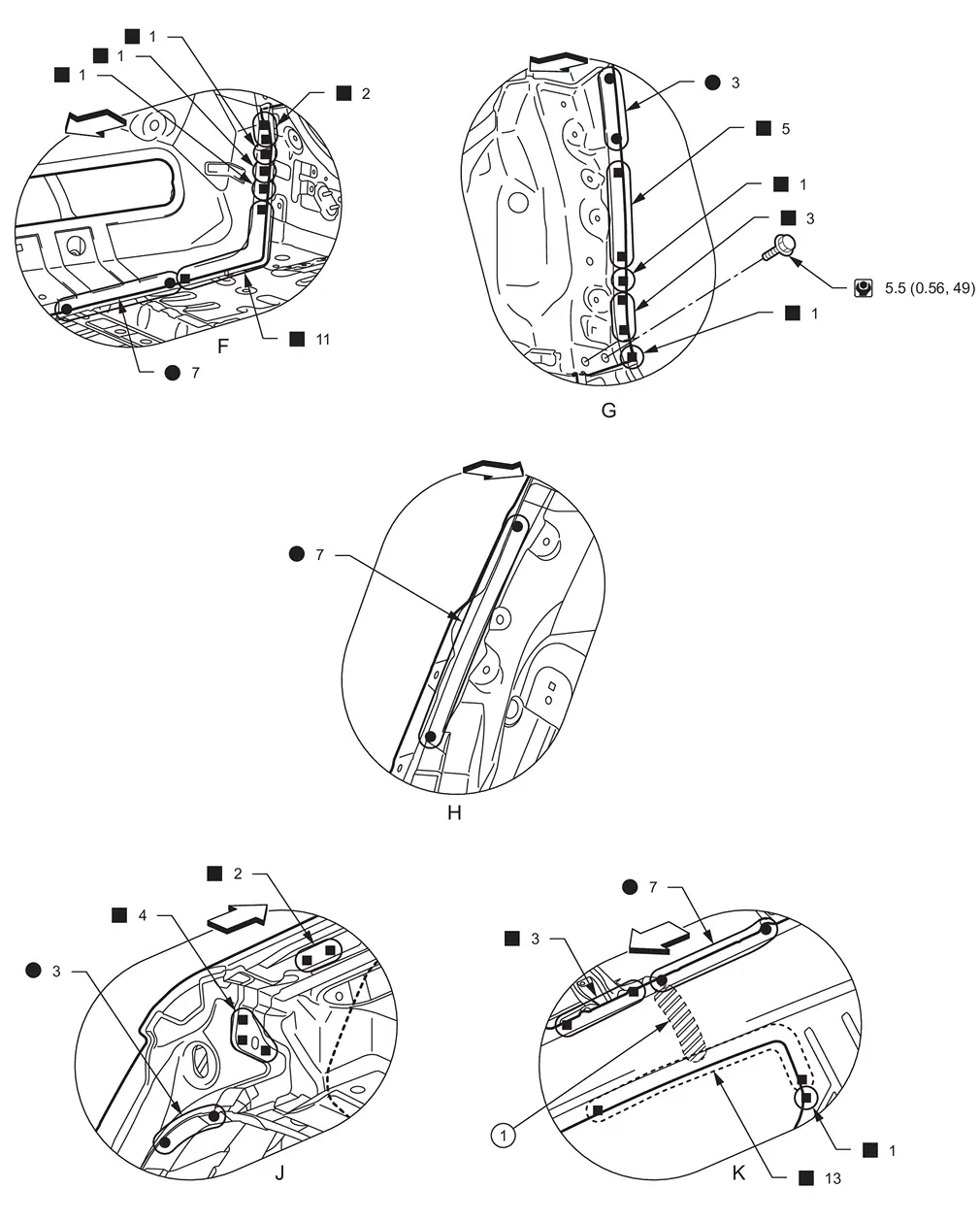
|
Urethane foam | ||||
| : vehicle front | |||||
| : Weld the parts onto the back of the component part. |
|||||
| : N•m (kg-m, in-lb) |
|||||
PARTIAL REPLACEMENT
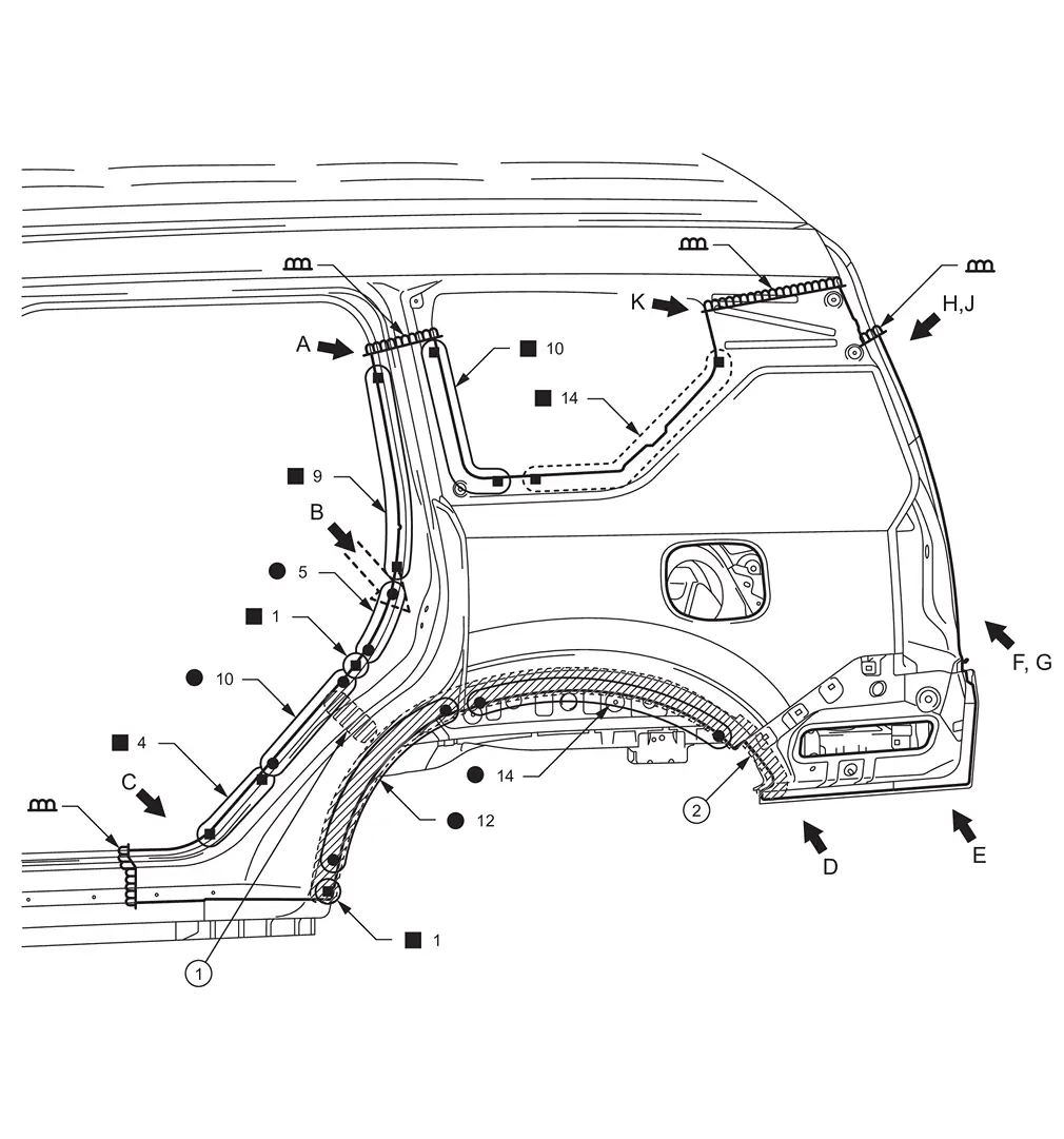
|
Urethane foam | |
Body sealing | ||
| : Weld the parts onto the back of the component part. |
|||||
| Replacement part | |||||
| • | Rear fender | ||||
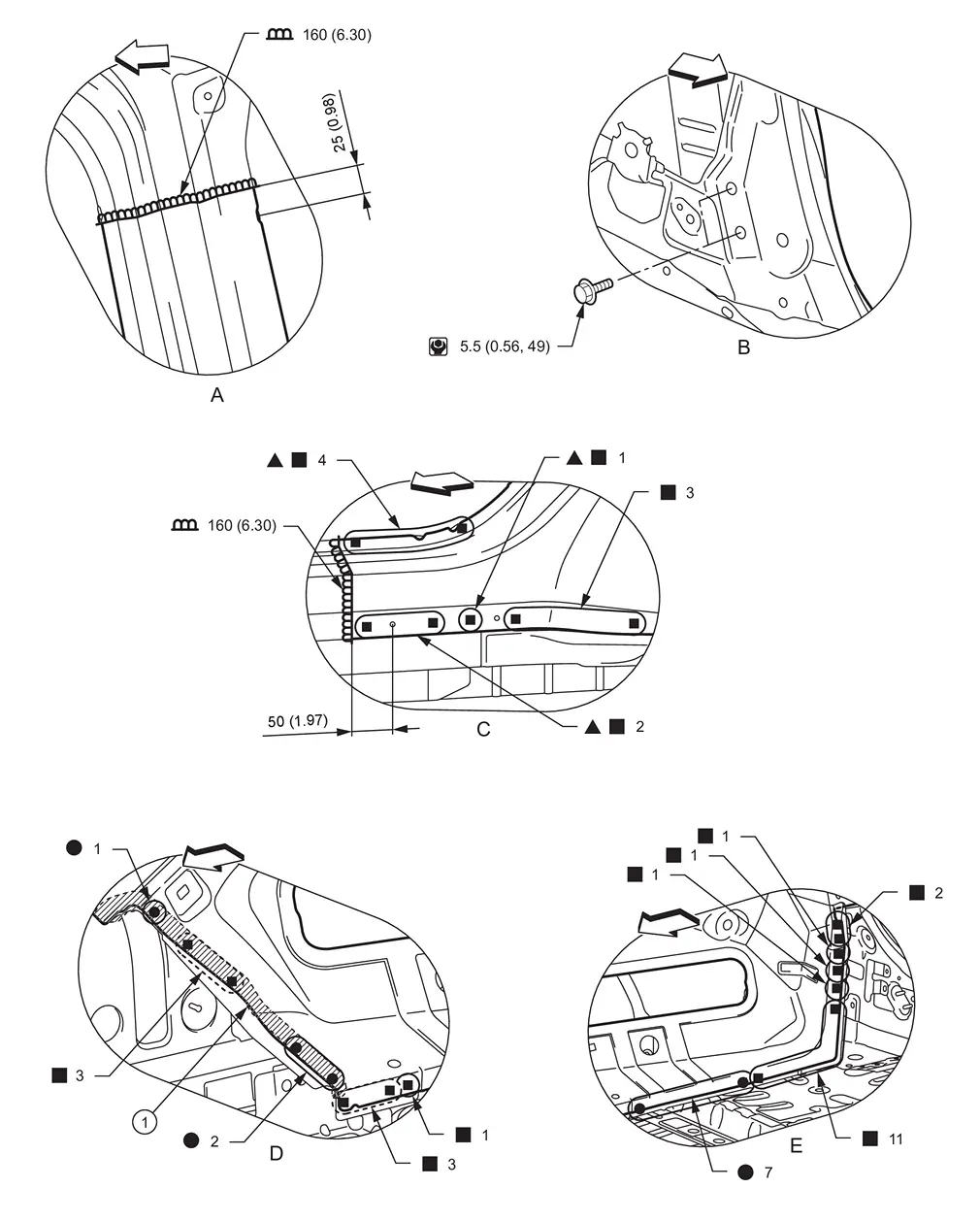
|
Body sealing | ||||
| Unit: mm (in) | |||||
| : vehicle front | |||||
| : Drill φ6 mm (0.24 in) hole for the plug welding hole (ultra high strength steel). | |||||
| : Weld the parts onto the back of the component part. |
|||||
| : N•m (kg-m, in-lb) |
|||||
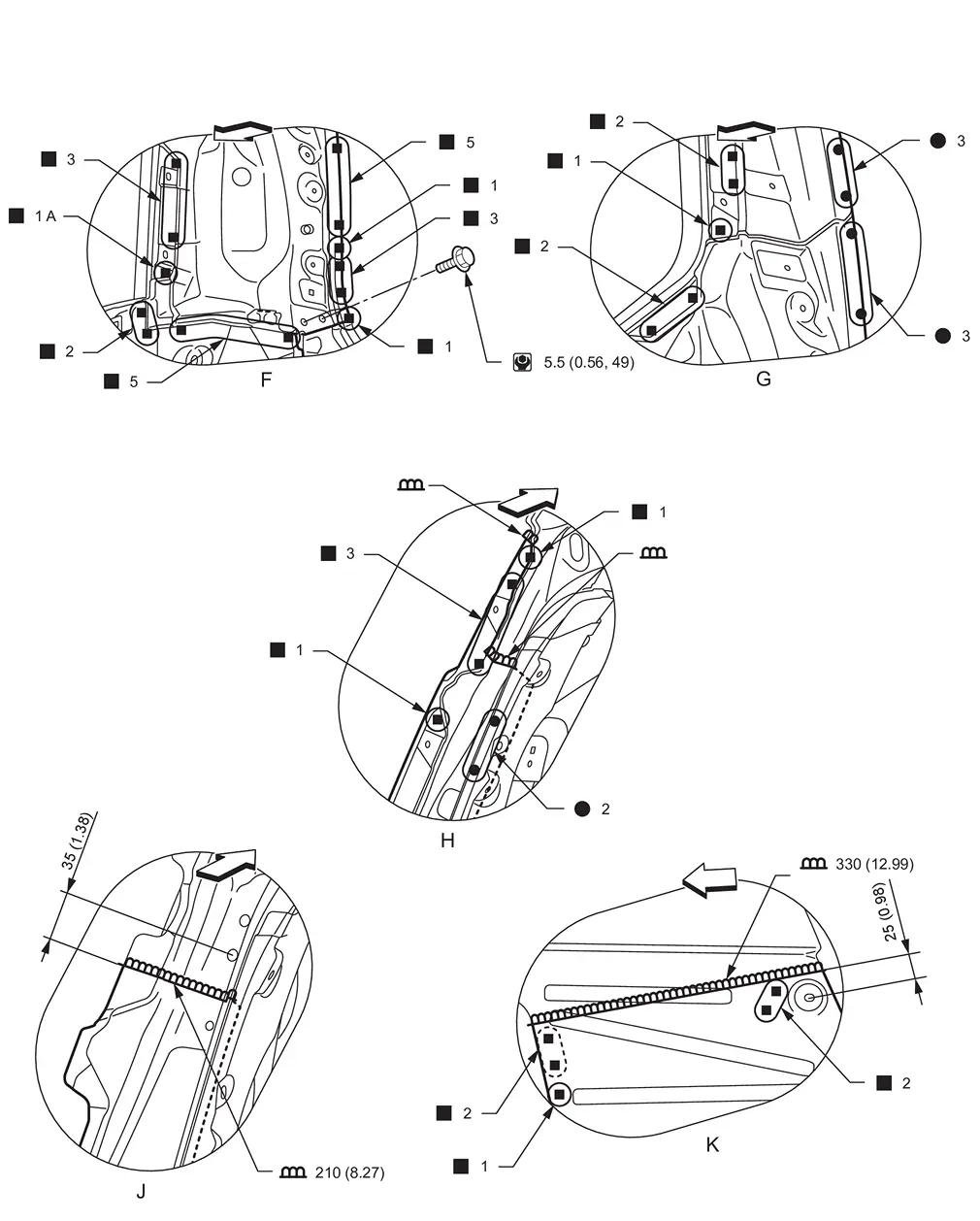
| Unit: mm (in) | |||||
| : vehicle front | |||||
| : Weld the parts onto the back of the component part. |
|||||
| : N•m (kg-m, in-lb) |
|||||
View J: Before installing outer side body
Rear Fender Extension
WARNING:
-
Jacking up or lift up the vehicle may the vehicle height to go down which cause a personal injury and/or damage to the air suspension component parts. Refer to Precaution for when Jacking and Lifting Up the vehicle with Electronic Air Suspension System.
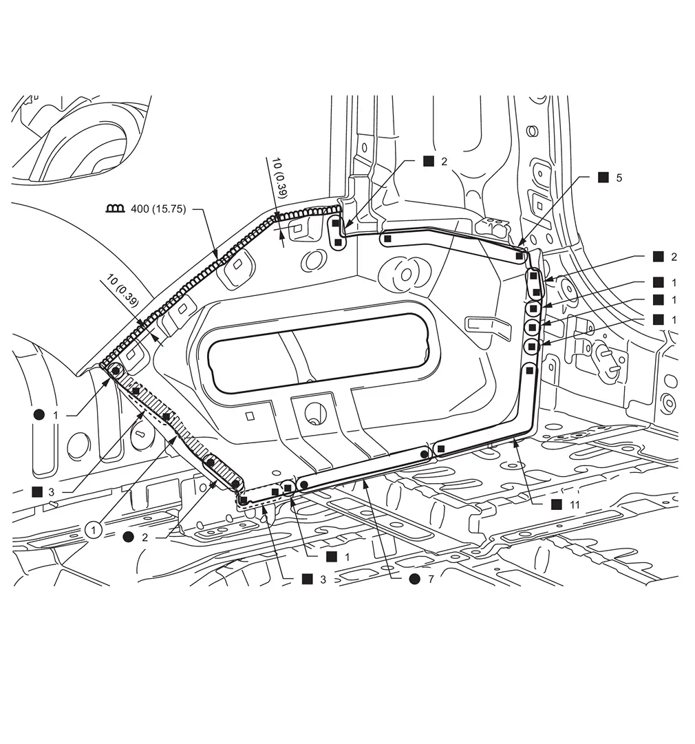
|
Body sealing | ||||
| Unit: mm (in) | |||||
| : Weld the parts onto the back of the component part. |
|||||
| Replacement part | |||||
| • | Rear fender extension | ||||
Outer Rear Wheelhouse
WARNING:
-
Jacking up or lift up the vehicle may the vehicle height to go down which cause a personal injury and/or damage to the air suspension component parts. Refer to Precaution for when Jacking and Lifting Up the vehicle with Electronic Air Suspension System.
Work after rear fender is removed.
Remove the outer rear sill reinforcement (reusable) from the vehicle for easier installation.
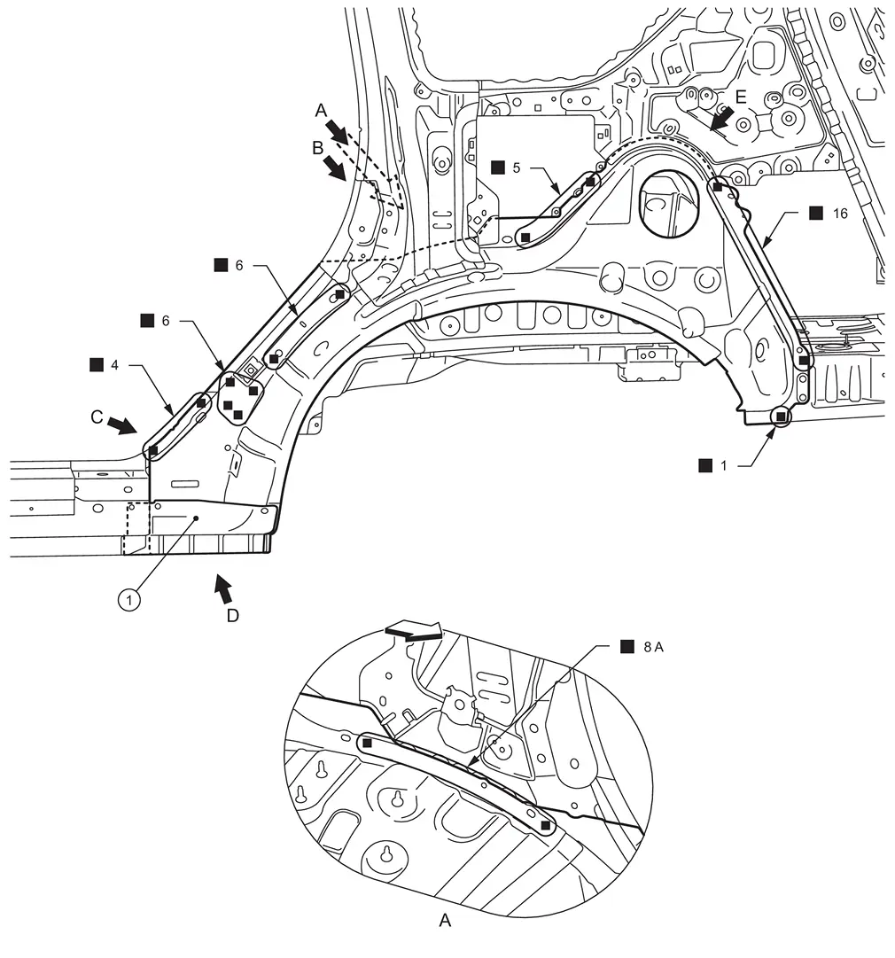
|
Outer rear sill reinforcement (reusable) | ||||
| : vehicle front | |||||
| Replacement part | |||||
| • | Outer rear wheelhouse | ||||
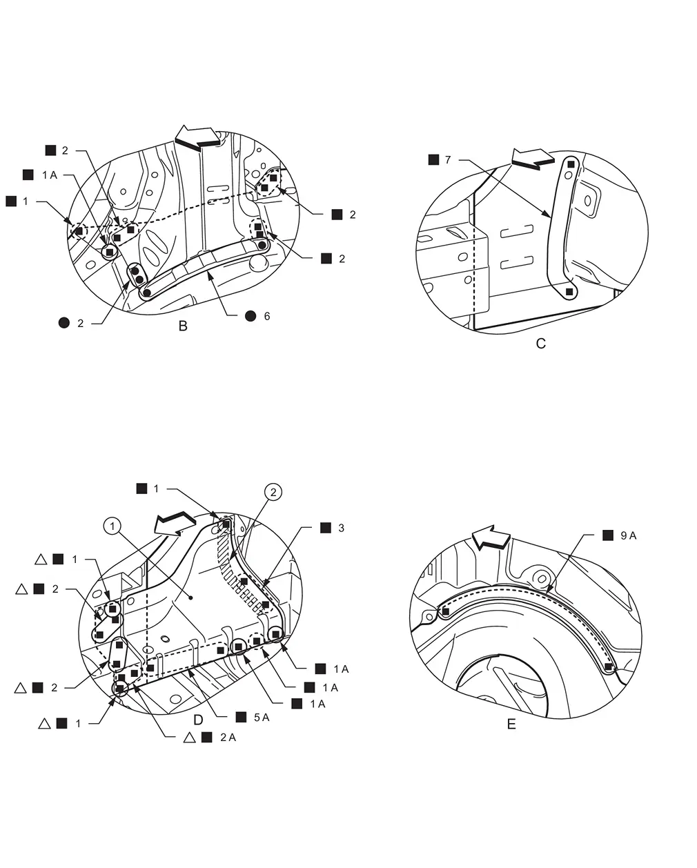
|
Outer rear sill reinforcement (reusable) | |
Body sealing | ||
|
: vehicle front
: Weld the parts onto the back of the component part. |
|||||
View C: Before installing outer rear sill reinforcement (reusable)
Inner Rear Wheelhouse
WARNING:
-
Jacking up or lift up the vehicle may the vehicle height to go down which cause a personal injury and/or damage to the air suspension component parts. Refer to Precaution for when Jacking and Lifting Up the vehicle with Electronic Air Suspension System.
WITH DYNAMIC DIGITAL SUSPENSION AND ELECTRONIC AIR SUSPENSION MODELS
Work after rear fender, outer rear sill reinforcement, and outer rear wheelhouse are removed.
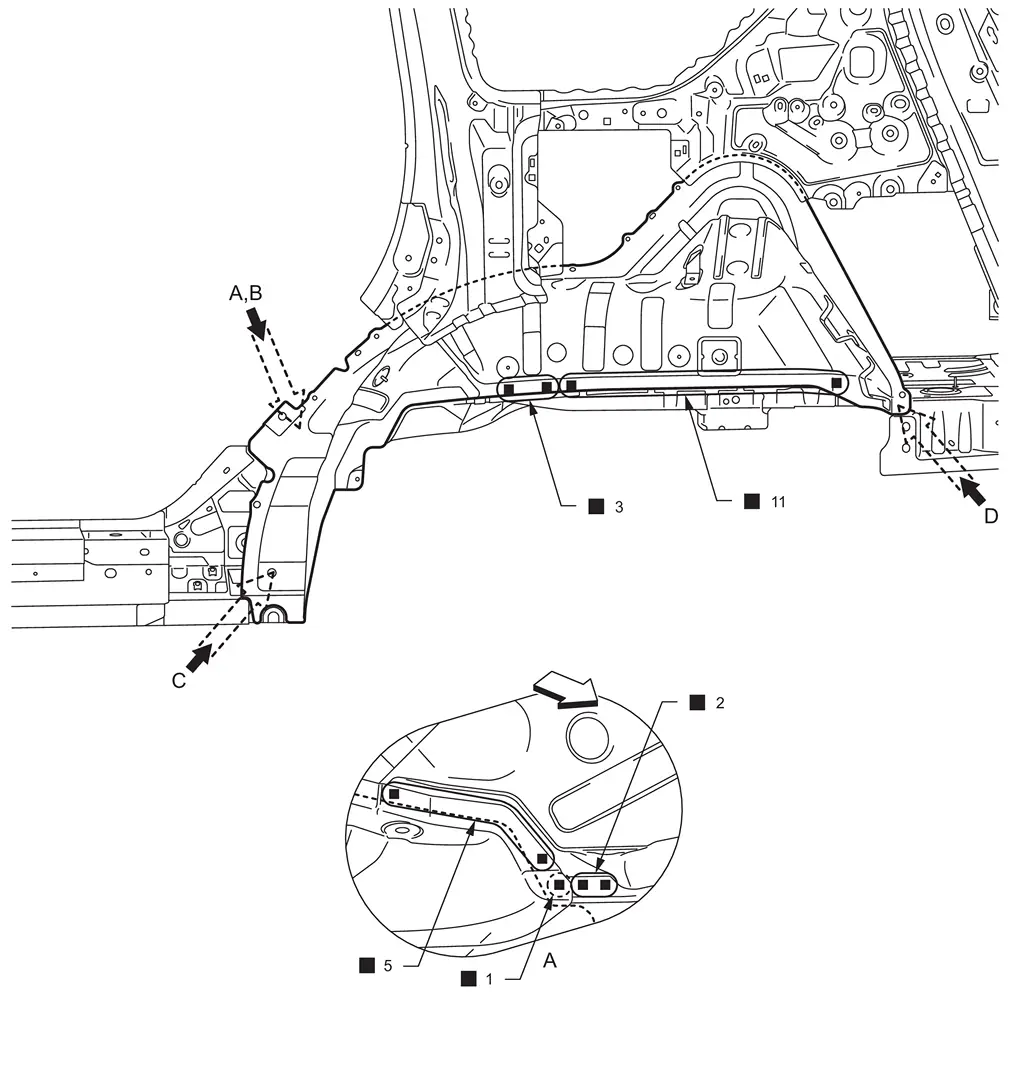
|
: vehicle front : Weld the parts onto the back of the component part. |
|||||
| Replacement part | |||||
| • | Inner rear wheelhouse | ||||
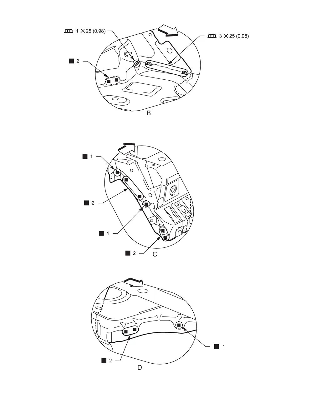
| Unit: mm (in) | |||||
|
: vehicle front : Weld the parts onto the back of the component part. |
|||||
WITHOUT DYNAMIC DIGITAL SUSPENSION AND ELECTRONIC AIR SUSPENSION MODELS
Work after rear fender, outer rear sill reinforcement, and outer rear wheelhouse are removed.
|
: vehicle front : Weld the parts onto the back of the component part. |
|||||
| Replacement part | |||||
| • | Inner rear wheelhouse | ||||
| Unit: mm (in) | |||||
|
: vehicle front : Weld the parts onto the back of the component part. |
|||||
Inner Rear Pillar Reinforcement
WARNING:
-
Jacking up or lift up the vehicle may the vehicle height to go down which cause a personal injury and/or damage to the air suspension component parts. Refer to Precaution for when Jacking and Lifting Up the vehicle with Electronic Air Suspension System.
Work after rear fender is removed.
|
Urethane foam | ||||
| Unit: mm (in) | |||||
|
: vehicle front : Weld the parts onto the back of the component part. |
|||||
| Replacement part | |||||
| • | Inner rear pillar reinforcement | ||||
Inner Rear Pillar
WARNING:
-
Jacking up or lift up the vehicle may the vehicle height to go down which cause a personal injury and/or damage to the air suspension component parts. Refer to Precaution for when Jacking and Lifting Up the vehicle with Electronic Air Suspension System.
Work after rear fender, inner rear pillar reinforcement, and back pillar reinforcement are removed.
Remove the welding point  for easier installation.
|
Urethane foam | ||||
|
: vehicle front : Weld the parts onto the back of the component part. |
|||||
| Replacement part | |||||
| • | Inner rear pillar | • | Inner back pillar | • | Inner rear side roof rail |
| • | Lower inner rear pillar | ||||
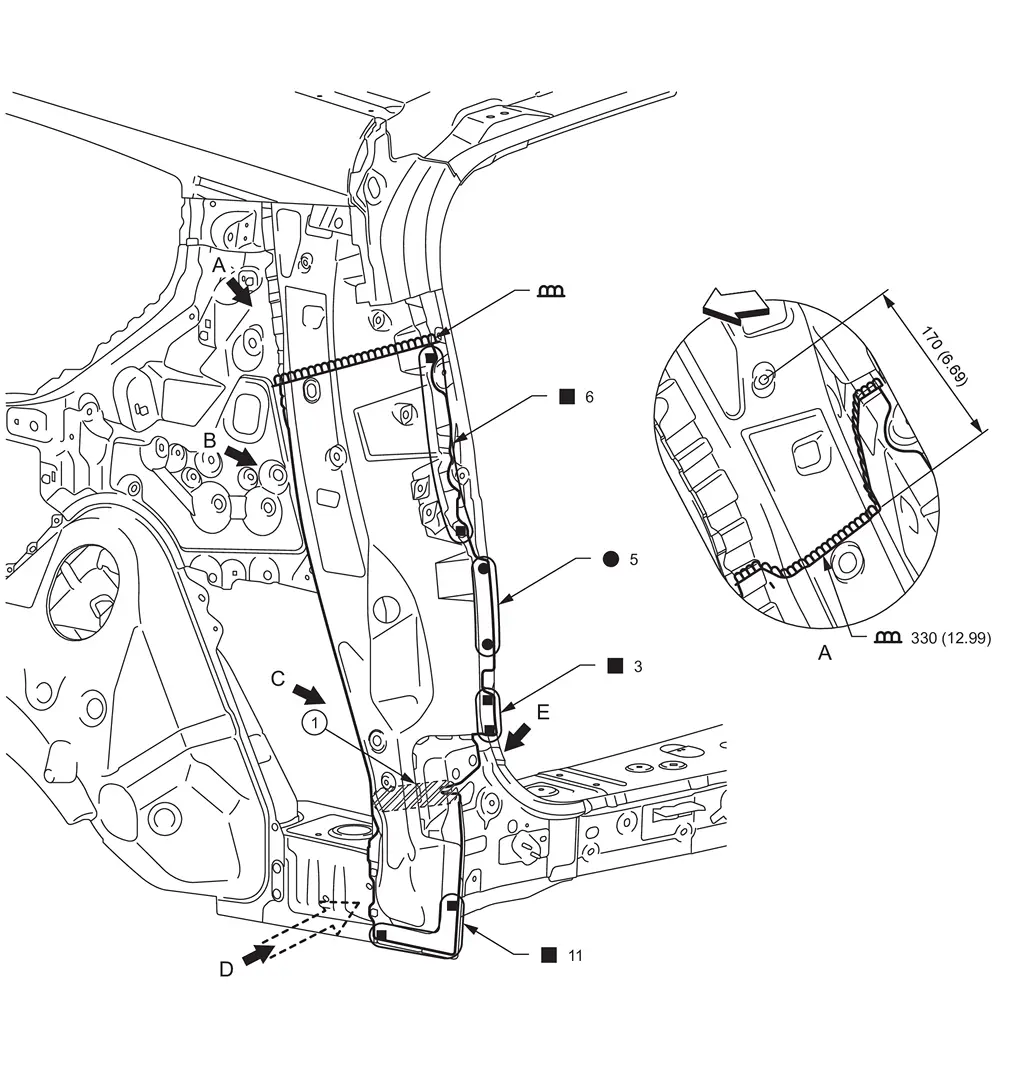
| Unit: mm (in) | |||||
|
: vehicle front
: N•m (kg-m, in-lb) |
|||||
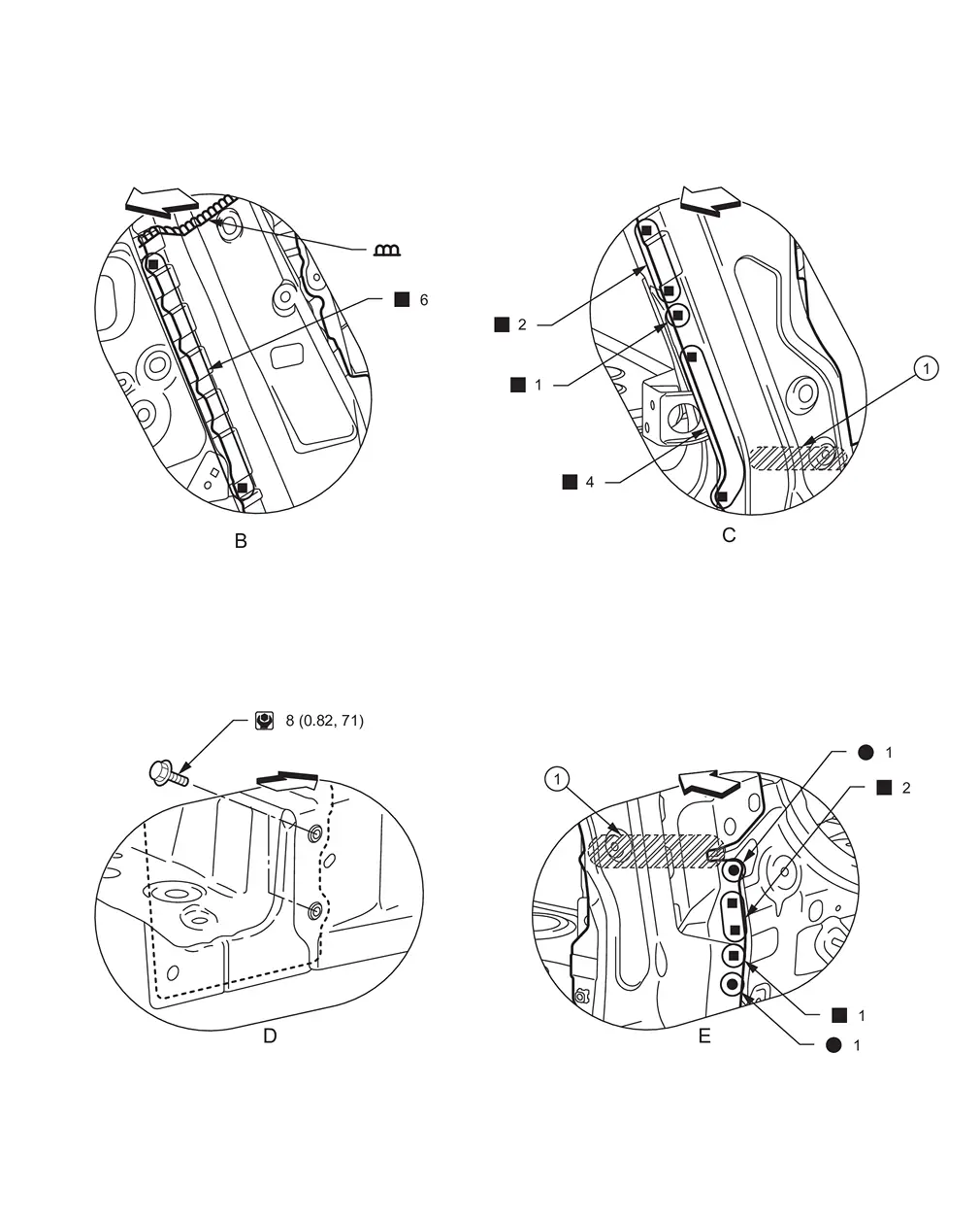
|
Urethane foam | ||||
| : vehicle front | |||||
| : N•m (kg-m, in-lb) |
|||||
Back Pillar Reinforcement
WARNING:
-
Jacking up or lift up the vehicle may the vehicle height to go down which cause a personal injury and/or damage to the air suspension component parts. Refer to Precaution for when Jacking and Lifting Up the vehicle with Electronic Air Suspension System.
Work after rear fender is removed.
|
Urethane foam | ||||
| Unit: mm (in) | |||||
| : vehicle front | |||||
| Replacement part | |||||
| • | Back pillar reinforcement | ||||
|
Urethane foam | ||||
| : vehicle front | |||||
| : N•m (kg-m, in-lb) |
|||||
Rear Panel
WARNING:
-
Jacking up or lift up the vehicle may the vehicle height to go down which cause a personal injury and/or damage to the air suspension component parts. Refer to Precaution for when Jacking and Lifting Up the vehicle with Electronic Air Suspension System.
| : vehicle front | |||||
| : Weld the parts onto the back of the component part. |
|||||
| : Welding method, the number of welding points, and the tightening torque apply to both sides of the vehicle. |
|||||
| : N•m (kg-m, in-lb) |
|||||
| Replacement part | |||||
| • | Rear end crossmember assembly | ||||
Rear End Crossmember
WARNING:
-
Jacking up or lift up the vehicle may the vehicle height to go down which cause a personal injury and/or damage to the air suspension component parts. Refer to Precaution for when Jacking and Lifting Up the vehicle with Electronic Air Suspension System.
|
Urethane foam | ||||
| Unit: mm (in) | |||||
| : vehicle front | |||||
| : Welding method, the number of welding points, and the distance in the figure apply to both sides of the vehicle. |
|||||
| : Urethane foam portion apply to both sides of the vehicle. |
|||||
| Replacement part | |||||
| • | Rear end crossmember assembly | • | Rear crossmember assembly | ||
|
Urethane foam | ||||
| Unit: mm (in) | |||||
| : vehicle front | |||||
| : Weld the parts onto the back of the component part. |
|||||
| : Welding method, the number of welding points, the distance in the figure, and the tightening torque apply to both sides of the vehicle. |
|||||
| : Urethane foam portion apply to both sides of the vehicle. |
|||||
| : N·m (kg-m, in-lb) |
|||||
| : vehicle front | |||||
| : Drill φ7 mm (0.28 in) hole for the plug welding hole (ultra high strength steel). |
|||||
| : Welding method, the number of welding points, and the tightening torque apply to both sides of the vehicle. |
|||||
| : N•m (kg-m, ft-lb) |
Rear Floor Rear
WARNING:
-
Jacking up or lift up the vehicle may the vehicle height to go down which cause a personal injury and/or damage to the air suspension component parts. Refer to Precaution for when Jacking and Lifting Up the vehicle with Electronic Air Suspension System.
WITH ProPILOT Assist 2.1 MODELS
Work after rear end crossmember is removed.
| : vehicle front | |||||
| : Drill φ6 mm (0.24 in) hole for the plug welding hole (ultra high strength steel). | |||||
| : Drill φ7 mm (0.28 in) hole for the plug welding hole (ultra high strength steel). |
|||||
| : Weld the parts onto the back of the component part. |
|||||
| : Welding method and the number of welding points apply to both sides of the vehicle. |
|||||
| Replacement part | |||||
| • | Rear floor rear | • | Rear side member | • | 3rd rear crossmember assembly |
| : vehicle front | |||||
| : Drill φ6 mm (0.24 in) hole for the plug welding hole (ultra high strength steel). | |||||
| : Drill φ7 mm (0.28 in) hole for the plug welding hole (ultra high strength steel). |
|||||
| : Drill φ8 mm (0.31 in) hole for the plug welding hole (ultra high strength steel). |
|||||
 : Drill φ11 mm (0.43 in) hole for the plug welding hole (ultra high strength steel). : Drill φ11 mm (0.43 in) hole for the plug welding hole (ultra high strength steel). |
|||||
| : Welding method and the number of welding points apply to both sides of the vehicle. |
WITHOUT ProPILOT Assist 2.1 MODELS
Work after rear end crossmember is removed.
| : vehicle front | |||||
| : Drill φ6 mm (0.24 in) hole for the plug welding hole (ultra high strength steel). | |||||
| : Drill φ7 mm (0.28 in) hole for the plug welding hole (ultra high strength steel). |
|||||
| : Weld the parts onto the back of the component part. |
|||||
| : Welding method and the number of welding points apply to both sides of the vehicle. |
|||||
| Replacement part | |||||
| • | Rear floor rear | • | Rear side member | • | 3rd rear crossmember assembly |
| : vehicle front | |||||
| : Drill φ6 mm (0.24 in) hole for the plug welding hole (ultra high strength steel). | |||||
| : Drill φ7 mm (0.28 in) hole for the plug welding hole (ultra high strength steel). |
|||||
| : Drill φ8 mm (0.31 in) hole for the plug welding hole (ultra high strength steel). |
|||||
| : Drill φ11 mm (0.43 in) hole for the plug welding hole (ultra high strength steel). |
|||||
| : Welding method and the number of welding points apply to both sides of the vehicle. |
Roof
WITHOUT SUNROOF MODELS
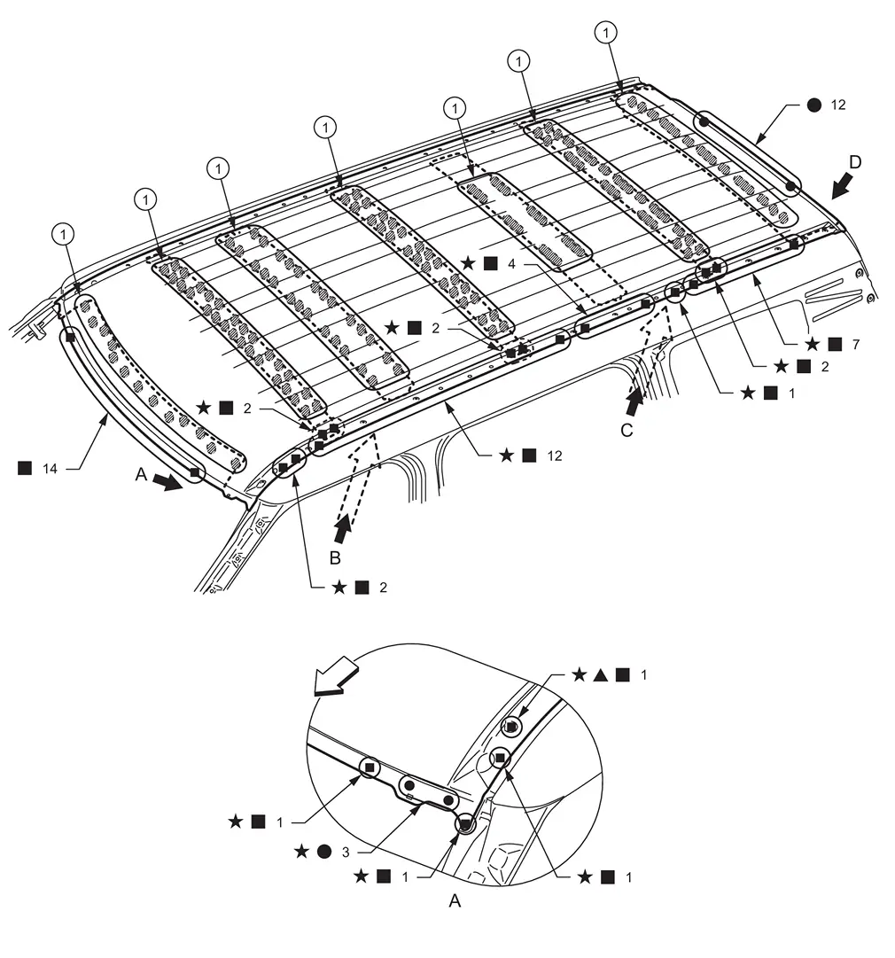
|
3M™ Urethane Seam Sealer 08368 or equivalent | ||||
| : vehicle front | |||||
| : Drill φ6 mm (0.24 in) hole for the plug welding hole (ultra high strength steel). | |||||
| : Weld the parts onto the back of the component part. |
|||||
| : Welding method and the number of welding points apply to both sides of the vehicle. |
|||||
| Replacement part | |||||
| • | Roof | • | Roof bow | • | 2nd roof bow |
| • | 3rd roof bow | • | 4th roof bow | • | 5th roof bow |
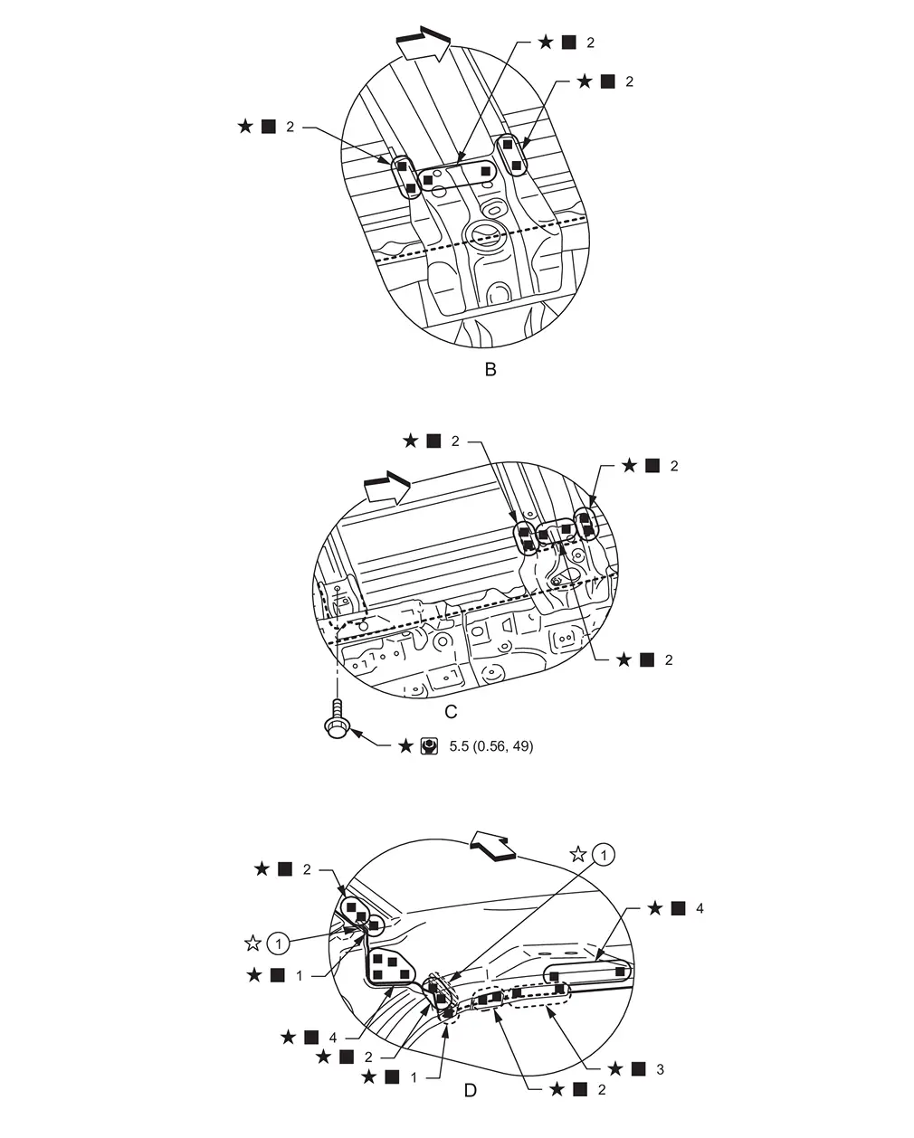
|
Adhesive | ||||
| : vehicle front | |||||
| : Weld the parts onto the back of the component part. |
|||||
| : Welding method, the number of welding points, and the tightening torque apply to both sides of the vehicle. |
|||||
| : Adhesive portion apply to both sides of the vehicle. |
|||||
| : N·m (kg-m, in-lb) |
|||||
WITH SUNROOF MODELS
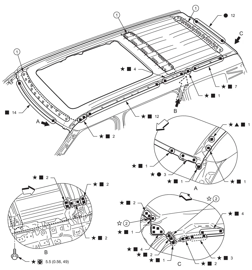
|
3M™ Urethane Seam Sealer 08368 or equivalent | |
Adhesive | ||
| : vehicle front | |||||
| : Drill φ6 mm (0.24 in) hole for the plug welding hole (ultra high strength steel). | |||||
| : Weld the parts onto the back of the component part. |
|||||
| : Welding method, the number of welding points, and the tightening torque apply to both sides of the vehicle. |
|||||
| : Adhesive portion apply to both sides of the vehicle. |
|||||
| : N·m (kg-m, in-lb) |
|||||
| Replacement part | |||||
| • | Roof assembly | • | 4th roof bow | ||
Roof Rail
Work after roof is removed.
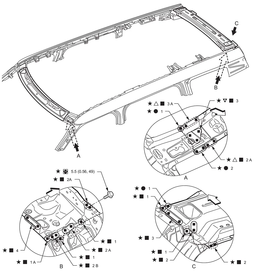
| : vehicle front | |||||
| : Drill φ8 mm (0.31 in) hole for the plug welding hole (ultra high strength steel). |
|||||
| : Drill φ11 mm (0.43 in) hole for the plug welding hole (ultra high strength steel). |
|||||
| : Weld the parts onto the back of the component part. |
|||||
| : Welding method, the number of welding points, and the tightening torque apply to both sides of the vehicle. |
|||||
| : N•m (kg-m, in-lb) |
|||||
| Replacement part | |||||
| • | Front roof rail | • | Rear roof rail | ||
Crush Horn
WARNING:
-
Jacking up or lift up the vehicle may the vehicle height to go down which cause a personal injury and/or damage to the air suspension component parts. Refer to Precaution for when Jacking and Lifting Up the vehicle with Electronic Air Suspension System.
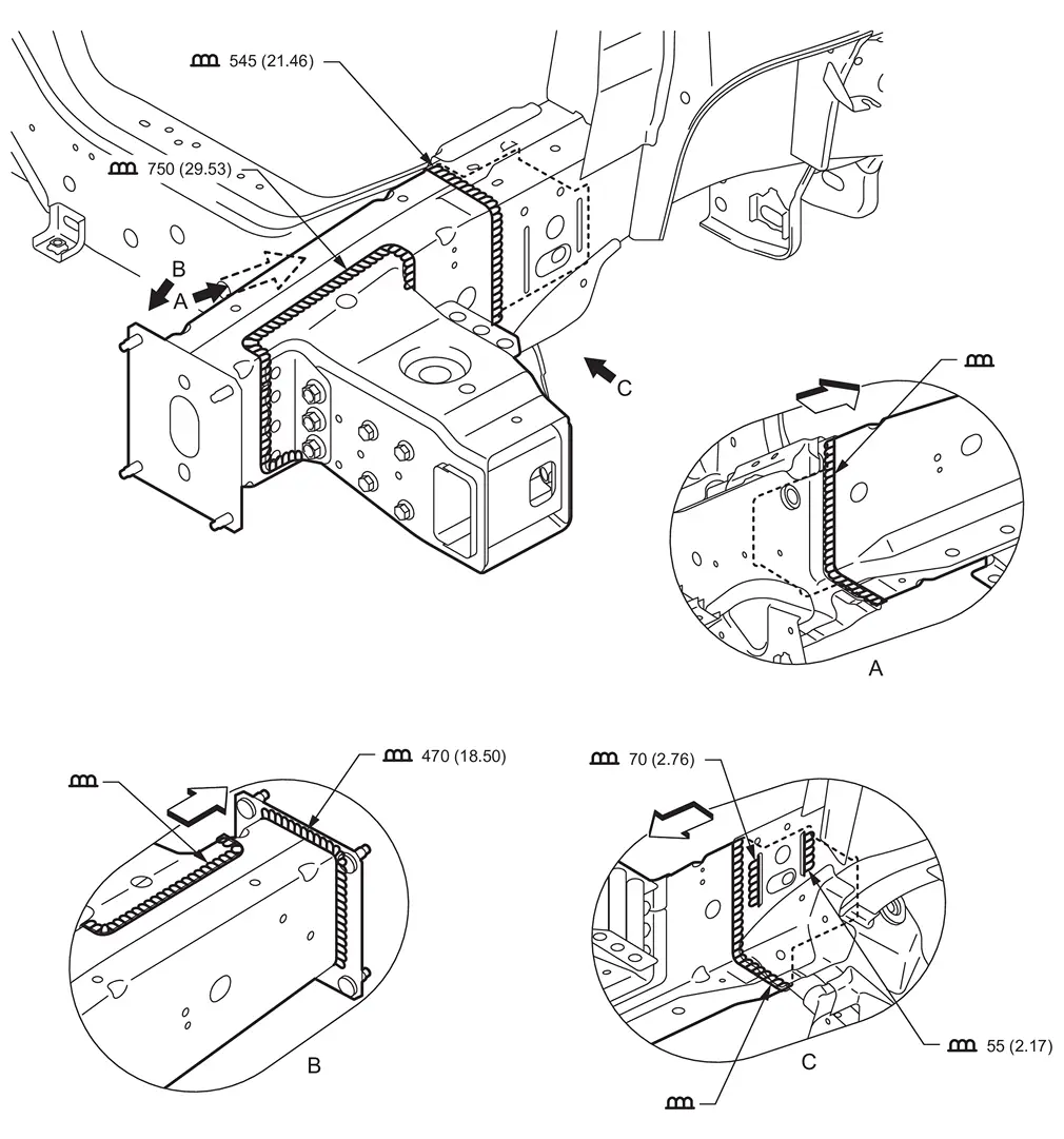
| Unit: mm (in) | |||||
| : vehicle front | |||||
| Replacement part | |||||
| • | Front side member assembly | • | 1st cab mounting bracket assembly | • | Front side member closing assembly (Front) |
Rear Frame
WARNING:
-
Jacking up or lift up the vehicle may the vehicle height to go down which cause a personal injury and/or damage to the air suspension component parts. Refer to Precaution for when Jacking and Lifting Up the vehicle with Electronic Air Suspension System.
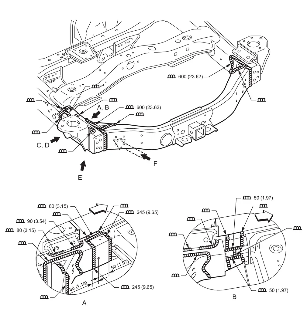
| Unit: mm (in) | |||||
| : vehicle front | |||||
| Replacement part | |||||
| • | Rear end crossmember assembly | • | Rear end gusset | • | Rear side member assembly (LH) |
| • | 5th cab mounting bracket (LH) | ||||
View B: Before installing inner rear side member
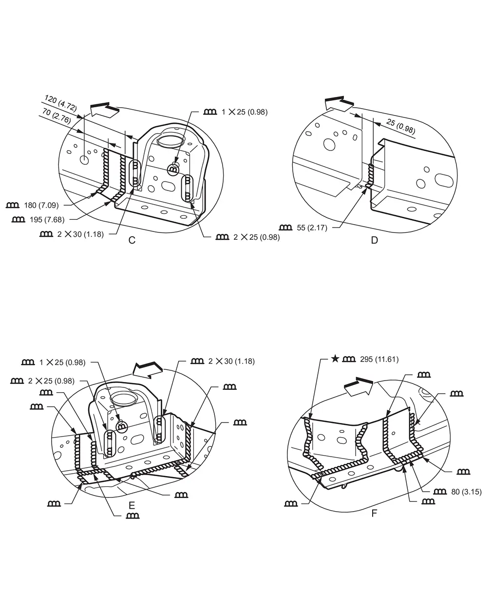
| Unit: mm (in) | |||||
| : vehicle front | |||||
| : Welding method and the distance in the figure apply to both sides of the vehicle. |
|||||
View C: Before installing inner rear side member
View D: Before installing inner rear side member, outer rear side member, and 5th cab mounting bracket (LH)
Other materials
Second Seat (bench Seat)
Exploded View
REMOVAL
Outer headrest
Second seat assembly
(RH seat)
Outside seat leg cover (RH seat)
Inside seat leg cover (RH seat)
Inside seat leg cover (LH seat)
Outside seat leg cover (LH seat)
Second seat assembly
(LH seat)
Center rail finisher
Center headrest
: P ...
Washer Level Switch
Exploded View
Washer tank
Packing
Washer level switch
Removal and Installation
WARNING:
REMOVALCAUTION:
When washer level switch is removed, washer fluid may come out so prepare a container to receive washer fluid and never allow washer fluid to be sprinkled.Remove fender protector RH. R ...
Precautions
Precaution for Supplemental Restraint System (SRS) "AIR BAG" and "SEAT BELT PRE-TENSIONER"
The Supplemental Restraint System such as “AIR BAG” and “SEAT BELT PRE-TENSIONER”, used along with a front seat belt, helps to reduce the risk or severity of injury to the driver and front passenger fo ...