
Nissan Armada 2025-2026 Service and Repair Manual: Three-dimensional Measuring Equipment
The equipment has function of the measurement to display the vehicle measuring points in three dimensions: height, width and length.
(1) UNIVERSAL JIG TYPE
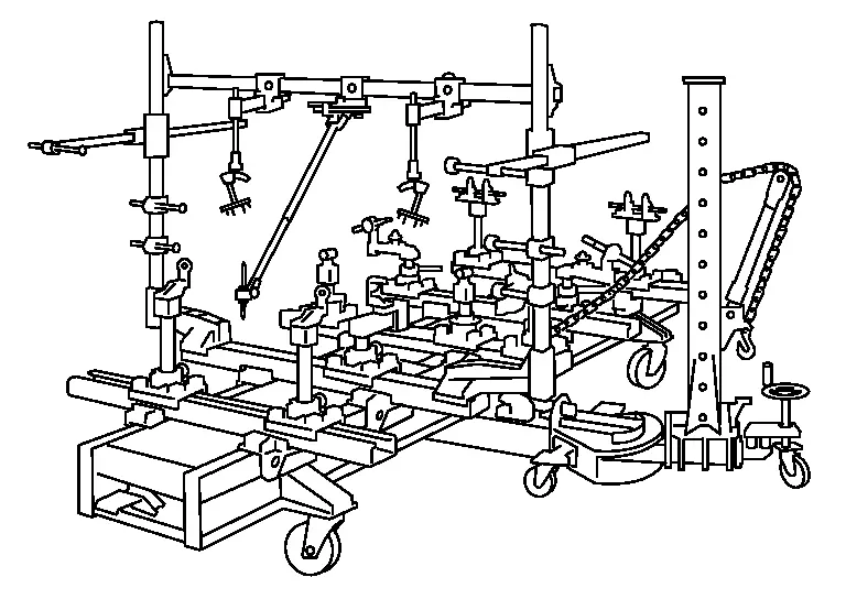
This is one of the universal jig type body straightening equipment functions. The jig is assembled according to the instruction card specific to each vehicle model. The jig, which can move forward/backward, left/right, and up/down, is anchored to each location on the underbody. The three-dimensional coordinates for the anchored point are read from the scale at the sliding base and jig head positions.
(2) UNIVERSAL MEASURING TYPE
The probe, which can move forward/backward, left/right, and up/down, is positioned on the frame. The three-dimensional coordinates at the measurement point and the distance between measurement holes can be measured by bringing the probe into contact with a locating hole on the body.
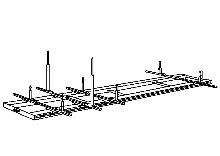
It is set on the straightening equipment for use.
(3) LASER TYPE
The three-dimensional coordinates are read using convergence and straight-line stability of a laser beam.
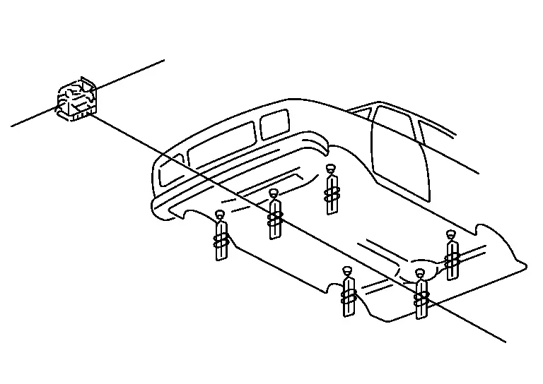
A laser beam is used for measurement. Once set, repair work can be performed during measurement.
(4) COMPUTER MEASURING TYPE
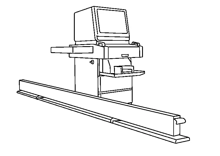
This is set on the straightening equipment. The probe which is mounted on flexible arm is positioned at each point of the vehicle body for measurement.
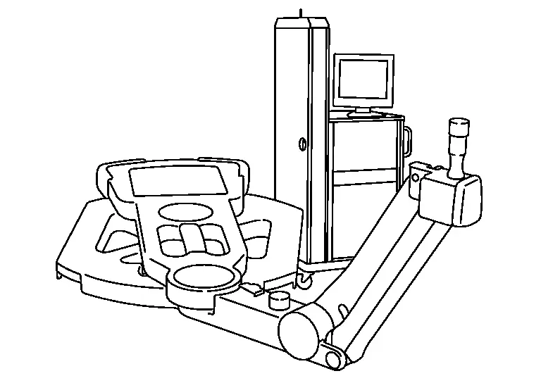
The computer compares the vehicle model data and the actual measurement data to identify the damage range and determine acceptability.
(5) ULTRASOUND TYPE
Ultrasound is transmitted from the probe, installed at the measurement point on the vehicle body, to the beam placed under the body in order to measure the three-dimensional coordinates at each measurement point.
 Tracking Gauge and Steel Tape
Measure the distance between two points. Before using the tracking gauge, check the measuring points with the steel tape.
(1) TRACKING GAUGE
Fit the tracking gauge correctly to the measuring point.
T ...

Other materials:
Refilling
WARNING:
The ignition switch OFF.
Recommended fluid and capacity: Refer to Fluids and Lubricants.
CAUTION:
Carefully fill the fluid. (Fill up for approximately 3 minutes.)
Leave the vehicle for 3 minutes, and check the fluid level again.
Install filler plug on transfer and tighten to the specif ...
Removal and Installation
REMOVAL
Remove rear center tray assembly. Refer to Removal and Installation.
Press the USB power socket fixing pawl from the back of the rear center console box to remove the USB power socket.
: Pawl
INSTALLATION
Note the following, and install in the reverse order of removal.
Align the cut out ...
Work Procedure
WRITING VEHICLE SPECIFICATION
With CONSULT
Perform writing vehicle specification to ABS actuator and electric unit (control unit) following "Automatic Configuration" procedure of "Configuration" according to CONSULT Operation Manual.
NOTE:
Log in the network according to CONSULT guidance.
>> ...

0.0067