
Nissan Armada 2025-2026 Service and Repair Manual: Types of MAG Welding
Welding Methods Using Gas Shielded Arc Welding
 NOTE:
NOTE:
Before MAG welding is performed on body components, some test welds should be carried out on offcuts of the replacement part that are not being used. When doing so, the welder settings can be optimized for the relevant material. The table shows some typical fault patterns and the relevant remedial measures.
Butt welding
The welding method that plugs the gap between two panels put together side-by-side. This method is used in welding for areas such as cut & joined areas on Quarter Panels and Rocker Panels. The finishing work is conducted the same as for plug welding.
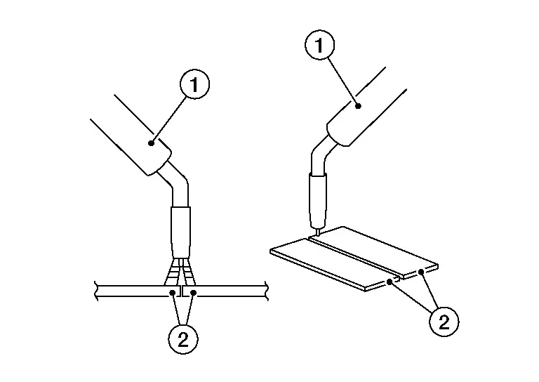
| 1 | :Torch |
| 2 | :Panel |
Fillet welding
The welding method where two panels are overlapped and the edge of one side is welded to join them together. Mainly being utilized in welding on frame type vehicles.
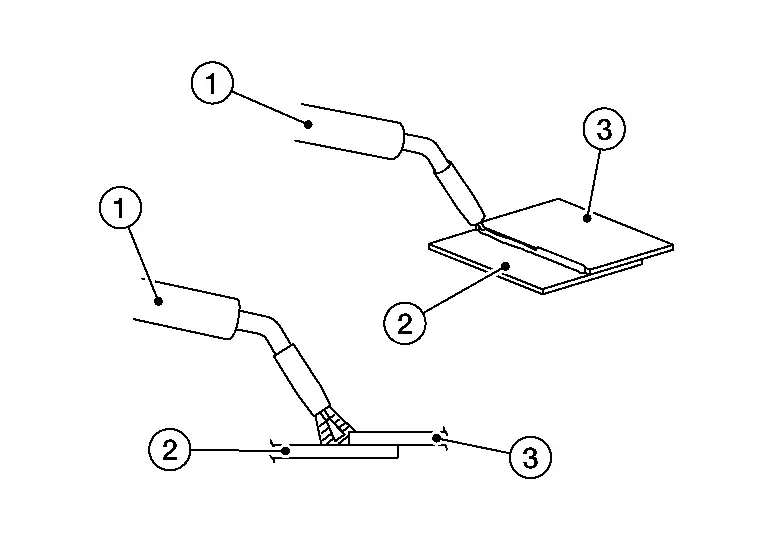
| 1 | :Torch |
| 2 | :Panel 1 |
| 3 | :Panel 2 |
Continuous welding
This welding process is suitable for sheet steel 2 mm (0.08 in) thick or over. If applied to thinner panels, it will cause melt-through.
Plug welding
Apply the torch at a right angle to the panel and quickly fill the hole with the molten metal intermittent welding generates oxide film, causing blowholes. When plug welding make a hole 5 mm - 6 mm (0.20 in - 0.24 in) in diameter in the upper of the two panels to be welded. Keep the upper panel and lower panel tightly together. For the finishing work, the raised welded area is smoothed out using a tool such as a belt sander.
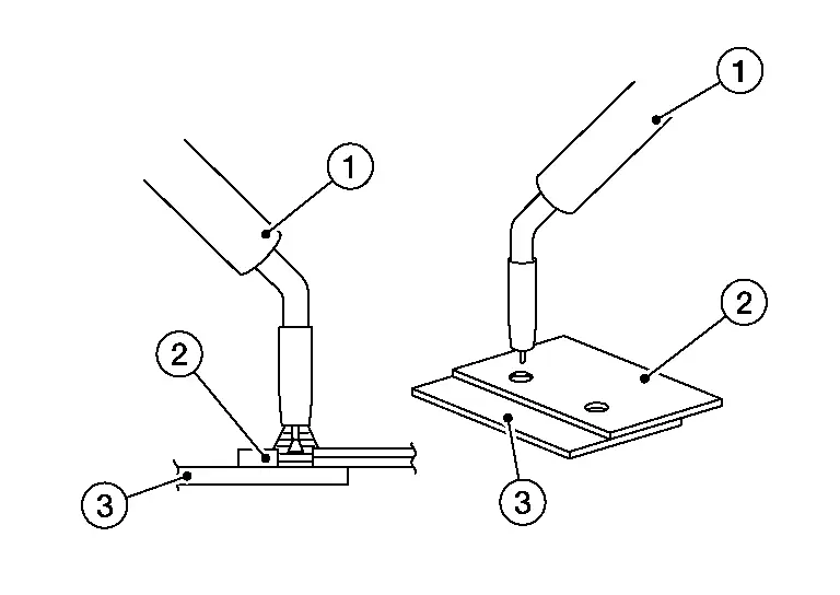
| 1 | :Torch |
| 2 | :Panel 1 |
| 3 | :Panel 2 |
Intermittent (step) welding
This method is suitable for thin or rusted panels to prevent thermal deformation and melt-through. In body repair, it is used as butt welding on partial panel replacements.
Before step welding, tack weld the panels to be welded to prevent strain and to align panel surfaces.
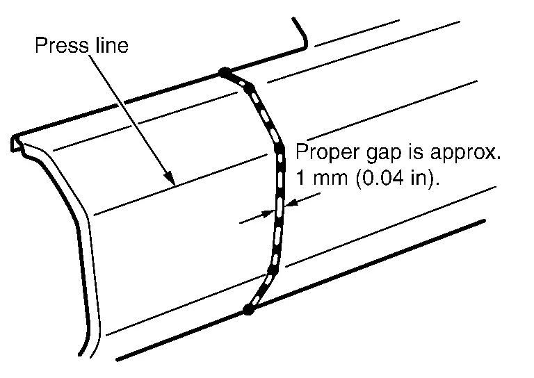
To do this, point weld and then fill in the spaces with short welding beads.
Remove all coatings from the replacement and joining panels within 1/2 inch (13mm) of the weld joint. This must be done on both the front and back side of the panels to prevent burnt coatings from interfering with corrosion protection later in the repair process.
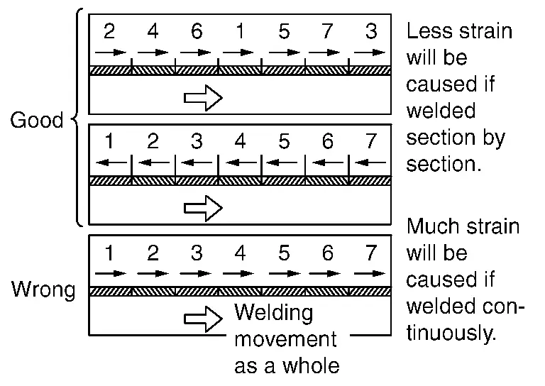
Long weld line will cause strain. Use the method as shown in the figure to reduce strain.
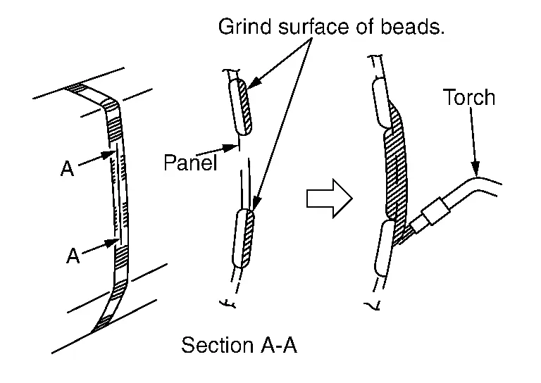
To fill the spaces between intermittently placed beads (A), grind the beads using a sander, then fill with molten metal. If this is done without grinding the surface of the beads, blowholes may result.
Separation process
Separating cuts on steel body components can be made with a body saw or an angle grinder with cutting disc. This should be done with a body saw if possible as angle grinders produce a large amount of sparks and the material may overheat at the cutting edges. It is essential to use a body saw when repairing the outer body skin for example partial replacement of a side panel. Sanding belts may also considered in some areas.
The blades of body saws, however, are only suitable up to a certain strength and material thickness. Separating cuts on body structure components made of high- strength or ultra-high-strength steels can only be made using an angle grinder with a cutting disc.
Opening spot-weld areas
To open spot-weld areas, the original welding spots are drilled out with a weld spot drill bit. A special weld spot drill bit with a controllable cutting depth must be used for this. This prevents the tool from drilling through the second sheet of metal. The sheet metal flanges are then separated from each other with a chisel.
Surface-grind the surface if necessary
Centre the punch mark on the welding spot
Drill out the welding spot
The heat during welding sometimes causes the surface of the welding spot to harden. In such cases, the welding spot must be sanded again before being drilled out. A belt sander can be used for this. Special welding spot cutters are required to loosen spot-weld areas on high-strength and ultra-high strength steels. Conventional weld spot drill bits are destroyed by use on high-strength and ultra high-strength steels. Alternatively, the welding spots can also be completely sanded down with a belt sander. When doing so, it must be ensured that the component underneath is not damaged.
Opening MAG weld seams and MIG soldered seams
MAG weld seams and MIG soldered seams are opened by being ground/sanded out with an angle grinder or belt sander. The remaining components must not be damaged during this process. The sheet metal flanges are then separated with a chisel. The procedure for high-strength and ultra-high-strength steels does not differ here from the procedure for steels with low strength. However, the abrasives are subject to significantly higher wear. Opening laser weld seams Laser weld seams are opened with an angle grinder. To do this, the laser weld seam is ground through together with the top metal sheet. It is essential to prevent damage to the metal sheet underneath during this process.
 Inspection of Welded Portions
Refer to the inspection method for spot welding. Refer to Inspection of Welded Portion.
Sample defects and welding conditions of MAG welding.
Defect Check points Remarks
Is correct wire selected?
...

Other materials:
Exploded View
Front camera (driving video recorder) Bracket Inside camera (driving video recorder) Inside camera bracket Cover ...
Removal and Installation
REMOVAL
Remove rear center tray assembly. Refer to Removal and Installation.
Press the USB power socket fixing pawl from the back of the rear center console box to remove the USB power socket.
: Pawl
INSTALLATION
Note the following, and install in the reverse order of removal.
Align the cut out ...
How to Check Terminal
HARNESS REPAIR KIT
When making a harness repair, refer to Connector Repair and Parts Lookup.
HOW TO PROBE CONNECTORS
Connector damage and an intermittent connection can result from improperly probing of the connector during circuit checks.
The probe of a digital multimeter (DMM) may not correctly fi ...

0.0069