
Nissan Armada 2025-2026 Service and Repair Manual: Unit Removal & Installation
WARNING:
WARNING:
Situate the vehicle on a flat and solid surface.
Place chocks at the front and back of rear wheels.
For engines not equipped with engine slingers, attach proper slingers and bolts described in PARTS CATALOG.
CAUTION:
Always be careful to work safely, and avoid forceful or uninstructed operations.
Never start working until exhaust system and engine coolant are cool enough.
If items or work required are not covered by the engine section, refer to the applicable sections.
Always use the support point specified for lifting.
Use either 2-pole lift type or separate type lift as much as possible. If board-on type is used for unavoidable reasons, support at rear axle jacking point with transmission jack or similar tool before starting work, in preparation for the backward shift of the center of gravity.
For supporting points for lifting and jacking point at rear axle, Refer to Garage Jack and Safety Stand
 NOTE:
NOTE:
When removing components such as hoses, tubes/lines, etc.,cap or plug openings to prevent fluid from spilling.
REMOVAL
Preparation
Remove tire assembly. Refer to ROAD WHEEL TIRE : Removal & Installation.
Remove fender protector. (RH and LH) Refer to Removal and Installation.
Remove hood assembly. Refer to Removal and Installation.
Remove engine cover. Refer to Removal and Installation.
Release fuel pressure. Refer to Work Procedure.
Disconnect battery cables from negative terminal. Refer to Exploded View.
Remove engine under cover front and front under cover using a power tool (commercial service tool). Refer to Removal and Installation and Removal and Installation.
Drain engine coolant from radiator. Refer to ENGINE COOLANT : Draining.
CAUTION:
Perform this step when engine is cold.
Never spill engine coolant on drive belt.
Discharge refrigerant from A/C circuit. Refer to Recycle Refrigerant.
Vehicle Underbody
Remove main muffler. Refer to EXHAUST SYSTEM : Removal & Installation.
Remove front propeller shaft (4WD models). Refer to Removal and Installation.
Remove rear propeller shaft. Refer to following :
2WD models: Refer to Removal and Installation.
4WD models with rear final drive (R240): Refer to Removal and Installation.
4WD models with rear final drive [R240(DL)]: Refer to Removal and Installation.
Remove front final drive assembly (4WD models). Refer to Removal and Installation.
Remove front stabilizer. Refer to Removal and Installation.
Remove rear engine mounting cross member. Refer to Exploded View.
Remove A/T assembly. Refer to following :
2WD models: Refer to Removal and Installation.
4WD models: Refer to Removal and Installation.
Remove 2nd catalyst converter (bank 1 and bank 2). Refer to Removal and Installation.
Disconnect the connection between the steering shaft and the lower joint. Refer to Removal and Installation.
Engine Room LH
Remove heat insulator (upper) bank 2 side. Refer to Removal & Installation
Remove catalyst converter (bank 2). Refer to Removal and Installation
Remove air duct and air cleaner assembly. Refer to Removal and Installation.
Remove radiator hose (upper) assembly  and reservoir tank hose
  .
.
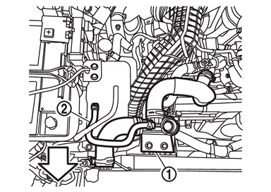
 | : Vehicle front |
Remove reservoir tank. Refer to RADIATOR : Exploded View.
Remove air inlet tube 2. Refer to Removal & Installation.
Remove electric water pump and bracket. Refer to Exploded View.
Remove inlet air duct 2 and reservoir tank tube as a set. Refer to following :
Refer to Exploded View.
Refer to RADIATOR : Exploded View.
Remove air inlet tube 1. Refer to Removal & Installation.
Remove radiator hose (lower). Refer to RADIATOR : Removal & Installation.
Remove high pressure flexible hose and low pressure flexible hose from A/C compressor, and temporarily fasten it on vehicle with a rope. Refer to Exploded View.
Disconnect fuel feed hose 1 from the high pressure fuel pump .
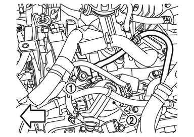
| : Vehicle front |
CAUTION:
Fit plugs onto disconnected hoses to prevent fuel leakage.
Remove EVAP hose 1 from the intake manifold side  .
.
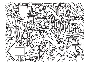
| : Vehicle front |
Remove each mounting bolt of the EVAP hose assembly and move to aside.
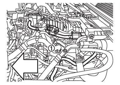
| : Vehicle front |
Remove water hose 6. Refer to Exploded View.
Remove ground cable. Refer to Exploded View.
Disconnect the electric intake valve timing control module harness connector. Refer to ELECTRIC INTAKE VALVE TIMING CONTROL MODULE : Removal & Installation
Engine Room RH
Remove water hose 2. Refer to Exploded View.
Remove nut of sub battery cable.
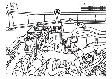
Disconnect the ECM harness connector and remove the ECM.
CAUTION:
Cover connectors with vinyl or similar material to protect against adhesion of foreign materials.
Disconnect the harness connector inside the fuse box .
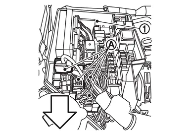
| : Vehicle front |
Remove front heater outlet pipe assembly. Refer to Removal and Installation.
Remove 12V sub battery (lithium ion battery) harness 1 bracket .
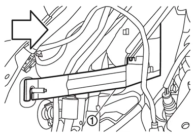
| : Vehicle front |
Remove front heater pipe assembly. Refer to Removal and Installation.
Remove low pressure pipe. Refer to Exploded View.
Remove battery and battery tray. Refer to Removal and Installation.
Remove heat insulator (upper) bank 1 side. Refer to Removal & Installation.
Remove catalyst converter (bank 1). Refer to Removal and Installation.
Disconnect the A/T fluid cooler hose connection. Refer to Removal and Installation.
Vehicle Front
Remove front grille and front grille upper.
OFF ROAD MODELS: Refer to Removal and Installation.
CITY MODELS: Refer to Removal and Installation.
Remove front bumper fascia.
OFF ROAD MODELS: Refer to Removal and Installation.
CITY MODELS: Refer to Removal and Installation.
Remove front combination lamp. (RH and LH) Refer to Removal and Installation.
Remove radiator air guide upper. Refer to Removal and Installation.
Remove active grille shutter. Refer to Removal and Installation.
Remove radiator air guide (RH) and radiator air guide (LH). Refer to Removal and Installation.
Remove front bumper reinforcement.
OFF ROAD MODELS: Refer to Removal and Installation.
CITY MODELS: Refer to Removal and Installation.
Remove A/T fluid cooler. Refer to Removal and Installation.
Remove engine cooling fan. Refer to ENGINE COOLING FAN : Removal & Installation
CAUTION:
Never damage or scratch radiator core when removing.
Remove radiator and condenser as a set. Refer to RADIATOR : Removal & Installation.
CAUTION:
Never damage or scratch radiator core when removing.
Remove hood lock. Refer to Removal and Installation.
Remove radiator core support. Refer to Removal and Installation
Remove A/T fluid cooler bracket. Refer to Removal and Installation.
Remove front bumper cross member. Refer to Exploded View.
Remove charge air cooler. Refer to Removal & Installation.
Separation Work
Install engine slingers into front of cylinder head (bank 1) and rear of cylinder head (bank 2).
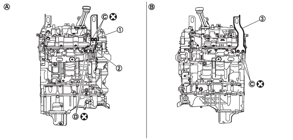
 | : Engine front slinger upper |
 | : Engine front slinger lower |
 | : Engine rear slinger |
| : Bank 1 |
 | : Bank 2 |
 | : Slinger bolts (Engine front slinger upper/Engine rear slinger) |
 | : Slinger bolts (Engine front slinger lower) |
 | : Always replace after every disassembly |
Tighten Slinger bolts
and to the torque specified below.
:28.0 N·m (2.9 kg-m, 21 ft-lb) NOTE:Remove mounting bolts
if necessary.
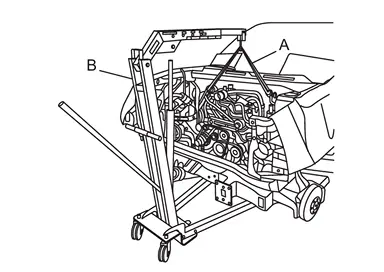
Install a belt slinger (A) to the engine slinga and set an mobile floor crane (B) or an suitable tool.
Remove clip .
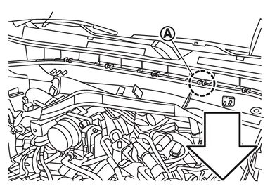
| : Vehicle front |
Lift with mobile floor crane or suitable tool until the sling belt is stretched.
CAUTION:
Do not lift the engine forcibly as the engine mount mounting bolts have not been removed.
Remove engine mounting bracket (RH and LH) mounting bolts.
Lift the engine using an mobile floor crane or suitable tools.
Make sure that the angle is as shown in figure  .
.
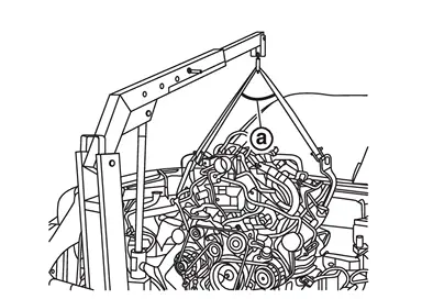
| : 60 degrees |
CAUTION:
Be careful not to interfere with the oil pan (lower) and the vehicle.
Make sure the belt slinger does not touch the cowl top cover.
Check that all connection points have been disconnected.
Keep in mind that the center of gravity of the vehicle changes.
Removal
Remove bolt .
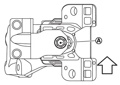
| : Vehicle front |
Remove stopper bracket (LH) using the following steps.Remove mounting bolts in the order shown in figure 2-1.
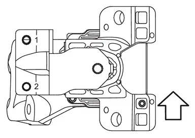
| : Vehicle front |
Remove engine mounting bracket (LH) using the following steps.Remove mounting bolts in the order shown in figure 4-1.
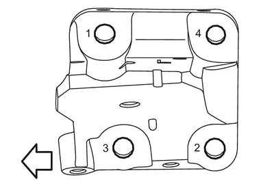
| : Vehicle front |
Remove bolt .
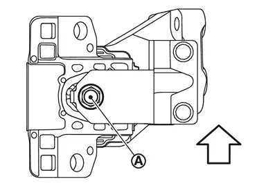
| : Vehicle front |
Remove stopper bracket (RH) using the following steps.Remove mounting bolts in the order shown in figure 2-1.
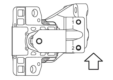
| : Vehicle front |
Remove engine mounting bracket (RH) using the following steps.Remove mounting bolts in the order shown in figure 4-1.
| : Vehicle front |
INSTALLATION
Note the following, and install in the reverse order of removal.
CAUTION:
Never allow engine oil to get on engine mounting insulator. Be careful not to damage engine mounting insulator.
Check that each mounting insulator is seated properly, and tighten mounting nuts and bolts.
If the engine assembly replaced, perform the following procedure.
IDLE AIR VOLUME LEARNING: Refer to Work Procedure.
THROTTLE VALVE CLOSED POSITION LEARNING: Refer to Work Procedure.
ELECTRIC IVT CONTROL ACTUATOR POSITION LEARNING: Refer to Work Procedure.
Preparation
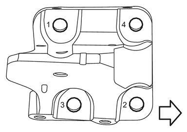
Install engine mounting bracket (RH) bolts as follows.Temporarily tighten in the order 1 to 4 shown in the figure.
| : Vehicle front |
| : Vehicle front |
| : 105.1 N·m (11.0 kg-m, 78 ft-lb) |
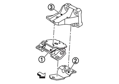
Install engine mounting insulator (RH) and stopper bracket (RH) to engine mounting bracket (RH) using the following steps.
| : Vehicle front |
.
| : Vehicle front |
Install stopper bracket (RH) using the following steps.Temporarily tighten in the order of 1-2 in the diagram.
| : Vehicle front |
| : Vehicle front |
| : 49.0 N·m (5.0 kg-m, 36 ft-lb) |
Tighten bolt to the specified torque.
| : Vehicle front |
| : 87.5 N·m (8.9 kg-m, 65 ft-lb) |
Install engine mounting bracket (LH) bolt using the following steps.Temporarily tighten in the order 1 to 4 shown in the figure.
| : Vehicle front |
| : Vehicle front |
| : 105.1 N·m (11.0 kg-m, 78 ft-lb) |
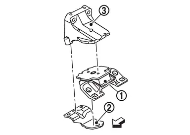
Install engine mounting insulator (LH) and stopper bracket (LH) to engine mounting bracket (LH) using the following steps.
| : Vehicle front |
.
| : Vehicle front |
Install stopper bracket (LH) using the following steps.Temporarily tighten in the order of 1-2 in the diagram.
| : Vehicle front |
| : Vehicle front |
| : 49.0 N·m (5.0 kg-m, 36 ft-lb) |
Tighten bolt to the specified torque.
| : Vehicle front |
| : 87.5 N·m (8.9 kg-m, 65 ft-lb) |
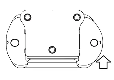
Install the engine mounting insulator (rear) bolt using the following steps.a First, temporarily tighten No. 2 in the diagram, then tighten in order 1-2 to the specified torque.
| : Vehicle front |
| : 87.5 N·m ( 8.9 kg-m, 65 ft-lb) |
Installation
NOTE:
Check the engine mounting insulator is not twisted.
Install engine mounting insulator (RH) bolts as follows.Temporarily tighten in the order of 1-2 shown in the figure.
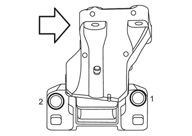
| : Vehicle front |
| : Vehicle front |
| : 110.0 N·m (11.0 kg-m, 81 ft-lb) |
Install e ngine mounting insulator (LH) bolt as follows.Temporarily tighten in the order of 1-2 shown in the figure.

| : Vehicle front |
| : Vehicle front |
| : 110.0 N·m (11.0 kg-m, 81 ft-lb) |
Install engine mounting insulator (rear) bolt to the rear engine mounting cross member as follows.First, temporarily tighten No.3 in the diagram first, then tighten to the specified torque in the order of 1-3.
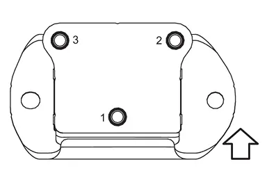
| : Vehicle front |
| : 87.5 N·m (8.9 kg-m, 65 ft-lb) |
 Exploded View
Engine mounting bracket (RH) Engine mounting insulator (RH) Stopper bracket (RH) Engine mounting bracket (LH) Engine mounting insulator (LH) Stopper bracket (LH) Engine mounting insulator (re ...
 Inspection
INSPECTION AFTER INSTALLATION
INSPECTION AFTER INSTALLATION
The following are procedures for checking fluid leakage, lubricant leakage.
Before starting engine, check oil/fluid levels including engine ...
Other materials:
Removal and Installation
CAUTION:
Never move intelligent rear view mirror beyond the movable range as the wiring may break.
: Vehicle front
intelligent rear view mirror movable range A : Standard position B : Less than 20° (upward adjustment range) C : Less than 20° (downward adjustment range) D : Less than ...
Basic Types of Damage
The first thing we look at is the dent. This is also the case when you repair a dent. You always should look at the damage first. The important thing to look at is the center of the dent. The depth of the dent is the important part. It tells you the following:
Difficulty of the repairTime of the rep ...
Inspection
AFTER A COLLISION
WARNING:
To avoid the risk of death or severe injury:
Replace any seat belt assembly (including anchor bolts) if:
The seat belt is damaged in an accident (i.e. torn webbing, bent retractor or guide, etc.).
The seat belt attaching point is damaged in an accident. Inspect the seat be ...

0.0073