Exploded View
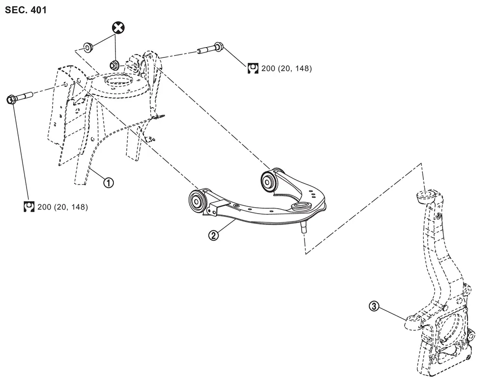
 |
Frame |  |
Upper link |  |
Steering knuckle |
 |
: Always replace after every disassembly. | ||||
 |
: N·m (kg-m, ft-lb) | ||||
Removal and Installation
WARNING:
-
Jacking up or lift up the vehicle may the vehicle height to go down which cause a personal injury and/or damage to the air suspension component parts. Refer to Precaution for when Jacking and Lifting Up the vehicle with Electronic Air Suspension System.
REMOVAL
Remove tires. Refer to ROAD WHEEL TIRE : Removal & Installation.
Remove height sensor from upper link. (With dynamic digital suspension and electronic air suspension) Refer to Removal and Installation.
Set suitable jack under lower link.
CAUTION:
Never damage lower link.
Remove brake hose bracket from steering knuckle. Refer to Removal and Installation.
Separate upper link from steering knuckle.
-
2WD models: Refer to Removal and Installation.
-
4WD models: Refer to Removal and Installation.
Remove part of fender protector. move fender protector in a place where it will not interfere with work. Refer to Removal and Installation.
Remove upper link mounting bolts, and remove upper link from vehicle.
Perform inspection after removal. Refer to Inspection.
INSTALLATION
Note the following, and install in the reverse order of removal.
-
Perform final tighting of upper (frame side) by the following procedures.
-
Measure between wheel center and fender arch (A).
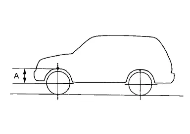
 NOTE:
NOTE:
Note the measurements.
-
Set the wheel chocks on the rear tires.
-
Jack up front of the vehicle and set the rigid rack.
-
Remove the front tires.
-
Set suitable jack (A) on the left and right steering knuckles
 (lower link ball joint fastening part).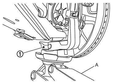
CAUTION:
Never damage threaded part of ball joint.
-
Jack up the left and right steering knuckles until the vehicle no longer floats off the rigid rack (A).
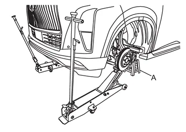
CAUTION:
-
Never damage steering knuckles.
-
Check the stable condition when using a suitable jack.
-
Never float the vehicle.
NOTE:
Jack up left and right at the same time.
-
-
Measure between wheel center and fender arch (A).
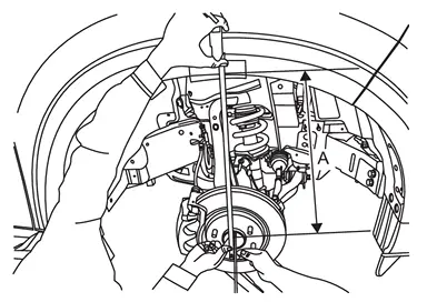
CAUTION:
-
Check the measurements are within +20 mm (0.79 in) from step 1.
-
If the measurements are +20 mm (0.79 in) or more, perform step 6 again.
-
-
Tight the mounting bolts of upper link (frame side) to the specified torque. Refer to Exploded View.
-
-
Perform inspection after installation. Refer to Inspection.
-
Perform adjustment after installation. Refer to Adjustment.
Inspection
INSPECTION AFTER REMOVAL
Appearance
Check the following items, and replace the part if necessary.
-
Upper link and bushing for deformation, cracks or damage.
-
Ball joint boot for cracks or other damage, and also for grease leakage.
Ball Joint Inspection
Manually move ball stud to confirm it moves smoothly with no binding.
Swing Torque Inspection
Move the ball joint at least ten times by hand to check for smooth movement.
Hook a spring balance (A) at cotter pin mounting hole. Confirm spring balance measurement value is within specifications when ball stud begins moving.
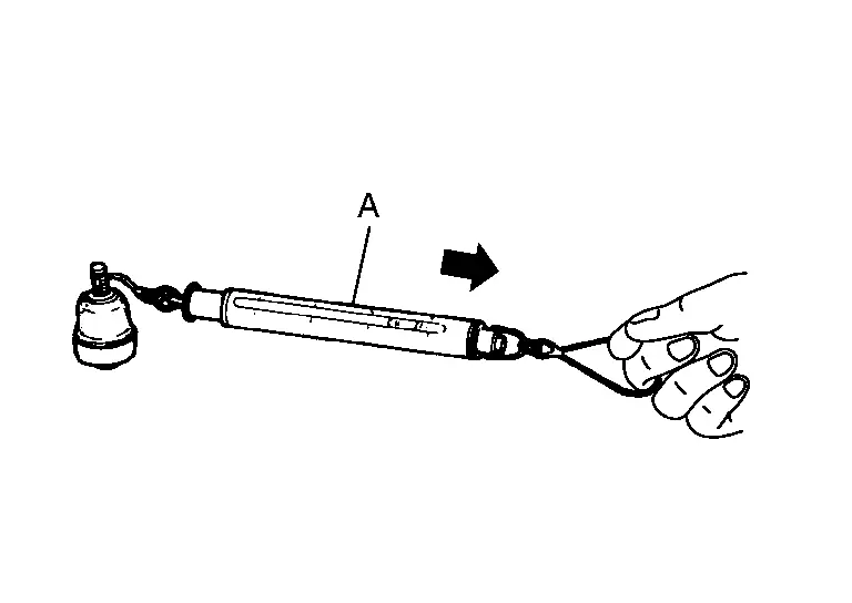
| Swing torque | : Refer to Ball Joint. |
-
If swing torque exceeds standard range, replace upper link assembly.
Rotating Torque Inspection
Move the ball joint at least ten times by hand to check for smooth movement.
Attach mounting nut to ball stud. Check that rotating torque is within specifications with a preload gauge [SST: ST3127S000 (NI-25765-A)] (A).
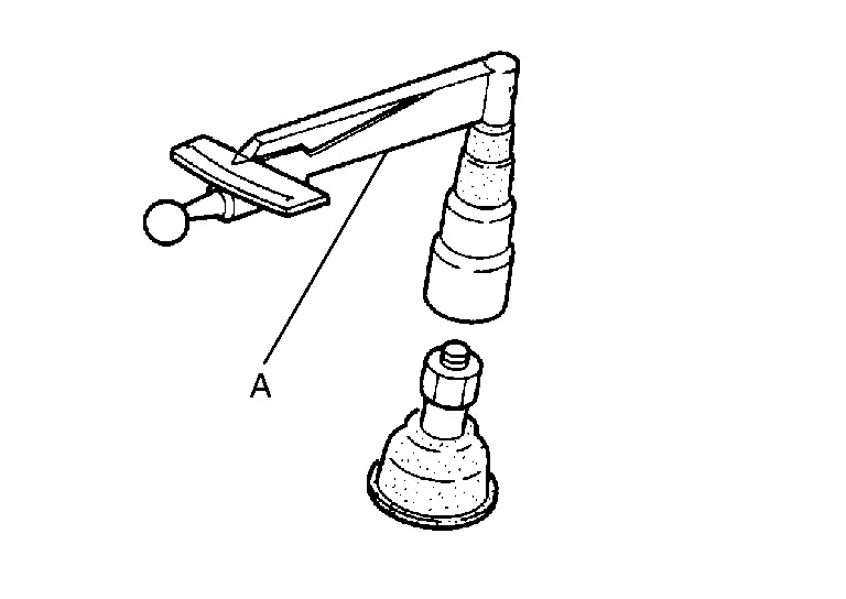
| Rotating toque | : Refer to Ball Joint. |
-
If rotating torque exceeds standard range, replace lower link assembly.
Axial End Play Inspection
Move the ball joint at least ten times by hand to check for smooth movement.
Move tip of ball stud in axial direction to check for looseness.
-
If there is axial end play, replace upper link assembly.
INSPECTION AFTER INSTALLATION
Check wheel alignment. Refer to Inspection.
Adjustment
ADJUSTMENT AFTER INSTALLATION
-
Adjust neutral position of steering angle sensor. Refer to Work Procedure.
-
Perform the height sensor calibration. (With dynamic digital suspension and electronic air suspension) Refer to Work Support.
Other materials
Drive belts
Water pump
Alternator
Drive belt automatic tensioner
Crankshaft pulley
Air conditioning compressor
WARNING
Always ensure the ignition switch is OFF before inspecting or servicing the
drive belts on your Nissan Armada. Unexpected engine rotation can cause serious
injury.
1. Ca ...
Low Tire Pressure Warning Lamp Does Not Turn Off
Description
The low tire pressure warning lamp does not turn OFF after several seconds is passed after engine starts.
Diagnosis Procedure
CHECK TIRE PRESSURE
Ignition switch ON.
CAUTION:
Never start the engine.
Check the tire pressure for all wheels and adjust to the specified value. Refer to TI ...
Back Door Hinge
Removal and Installation
REMOVALRemove back door assembly. Refer to Removal and Installation.
Remove back door hinge mounting nuts, and then remove back door hinge.INSTALLATIONNote the following items, and then install in the reverse order of removal.CAUTION:
Before installation, apply anticorrosi ...