
Nissan Armada 2025-2026 Service and Repair Manual: Work Procedure
Application Notice
| Type | Description |
|---|---|
| TYPE 1 | When using KV99112700 for radar alignment. Refer to Description. |
| TYPE 2 | When using 1-20-2851-1 for radar alignment. Refer to Description. |
TYPE 1
Description
A 4-wheel vehicle alignment must be performed before proceeding with radar alignment procedure.
WARNING:
Radio waves could adversely affect electric medical equipment. Those who use a pacemaker should contact the electric medical equipment manufacturer for the possible influences before use.
CAUTION:
The system does not operate normally unless the radar alignment is performed. Always perform it.
Set the target board (SST: KV99112700) to the correct position in front of the vehicle.
Set the radar alignment mode (“MILLIWAVE RADAR ADJUST” on “Work support”) with CONSULT, and then perform the adjustment according to the display. (Distance sensor automatically adjusts.)
CAUTION:
For radar alignment procedure, choose a level location with a few meter of working space in front and surrounding the vehicle.
Vehicle must be stationary and unoccupied during the whole alignment procedure.
Any slight vibration during the alignment procedure can cause the test to fail. If this happens, you will have to restart the alignment process.
The ignition switch must be in the ON position.
The battery voltage must not fall below 12 volts during the whole alignment procedure. Failure to maintain adequate battery voltage will cause the test to fail. If this happens, you will have to restart the alignment process.
The target board must be set in front of the vehicle facing the sensor.
Adjust the radar alignment with CONSULT. (The radar alignment procedure cannot be adjusted without CONSULT.)
Never enter the vehicle during radar alignment.
Never block the area between the radar and the target board at any time during the alignment process.
Accurate steering wheel setting is crucial. Once set, do not disturb the steering wheel for the remainder of the alignment procedure.
For proper system operation and adjustment, all vehicle wheels must be of the same size.
Preparation
ADVANCE PREPARATION FOR RADAR ALIGNMENT
Adjust all tire pressure to the specified value.
Empty the vehicle. (Remove any luggage from the passenger compartment, trunk room, etc.)
Set shift position to “P” position, and release the parking brake.
Clean the distance sensor area
 of the front bumper.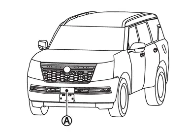
GO TO 2.
RADAR ALIGNMENT OPERATION AREA
Position the vehicle in a place that is level and where  area can be secured.
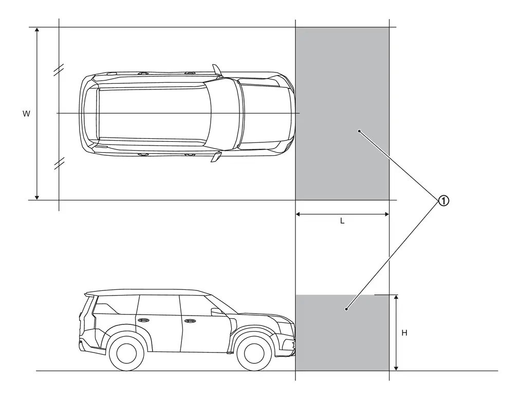
| W | : 3000 mm (118.11 in) |
| L | : 2000 mm (78.74 in) |
| H | : 2000 mm (78.74 in) |
 NOTE:
NOTE:
is a no object zone.
Go to Setting The Target Board.
Setting The Target Board
Accurate adjustment of the radar alignment requires that the target board be accurately positioned.
CAUTION:
If the radar alignment is adjusted with the target board in the incorrect position, the AEB/ProPILOT Assist/I-FCW systems do not function normally.
TARGET BOARD HEIGHT ADJUSTMENT
Set the target board up to adjustable maximum height.
>>GO TO 2.
PREPARATION OF SETTING TARGET BOARD (1)
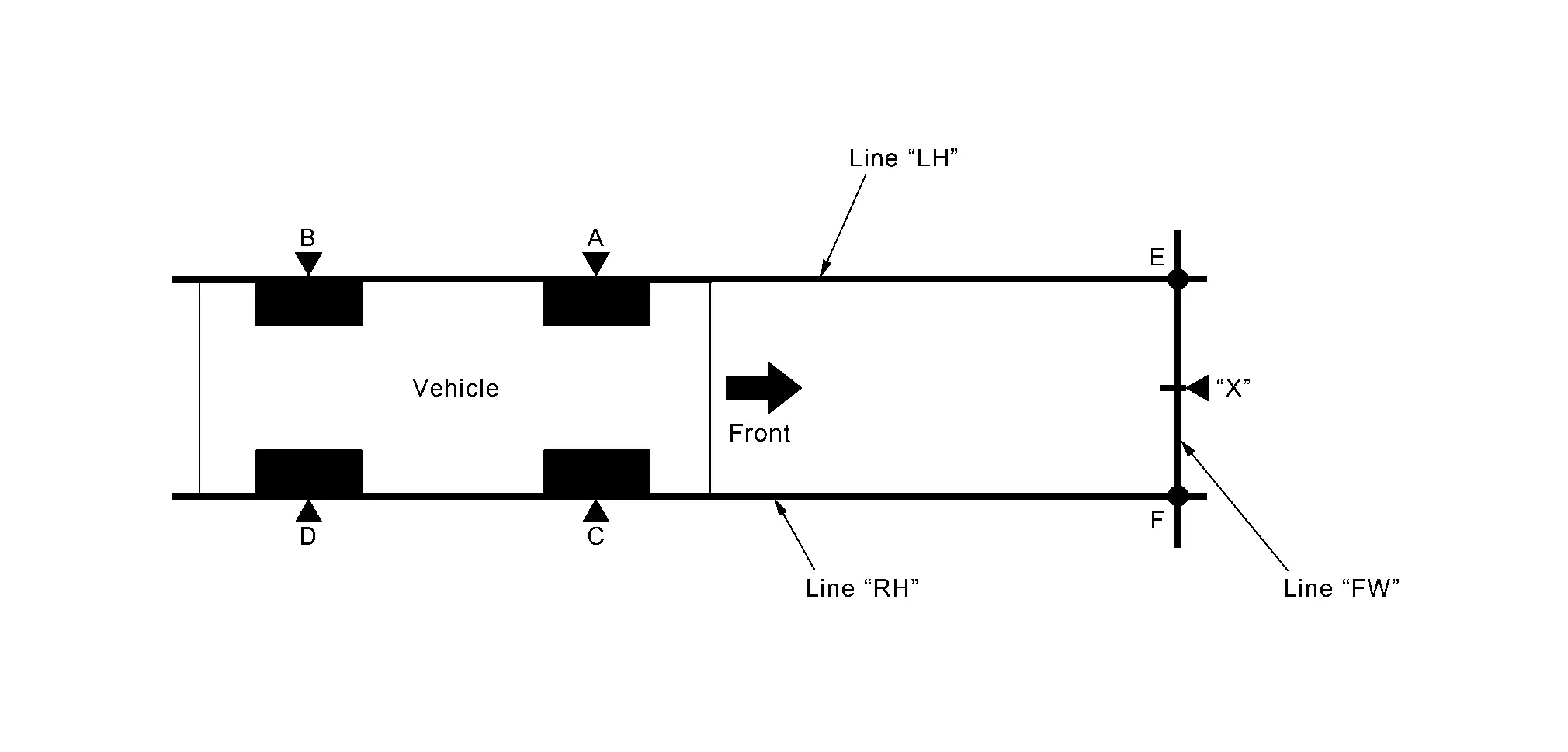
| “A”–“E” (“C”–“F”) | : 2000 mm (78.7 in) |
Mark points “A”, “B”, “C” and “D”at the center of the lateral surface of each wheels.
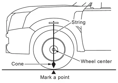 NOTE:
NOTE:Hang a string with a cone from the fender so as to pass through the center of wheel, and then mark a point at the center of the lateral surface of the wheel.
Draw line “LH” passing through points “A” and “B” on the left side of vehicle.
NOTE:Approximately 2 m (6.56 ft) or more from the front end of vehicle.
Mark point “E” on the line “LH” at the positions 2000 mm (78.7 in) from point “A”.
Draw line “RH” passing through points “C” and “D” on the right side of vehicle in the same way as step 2.
NOTE:Approximately 2 m (6.56 ft) or more from the front end of vehicle.
Mark point “F” on the line “RH” at the positions 2000 mm (78.7 in) from point “C”.
Draw line “FW” passing through the points “E” and “F” on the front side of vehicle.
Mark point “X” at the center of point “E” and “F” on the line “FW”.
CAUTION:
Make sure that “E” to “X” is equal to “F” to “X”.
GO TO 3.
SETTING TARGET BOARD
Place the center of target board on point “G” at line “E-F” and install the target board.
CAUTION:
For performing the radar alignment correctly, securely install (target board) to be parallel with the “E-F” line.
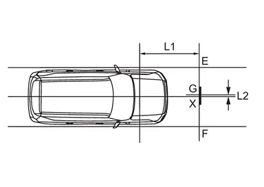
| L1 | : 2000 mm (78.7 in) |
| L2 | : 0 mm (0 in) |
GO TO 4.
CHECK THE TARGET BOARD INSTALLATION AREA
Do not place anything other than target board in the space shown in the figure (view from top).
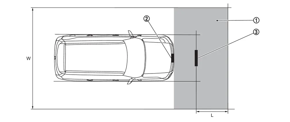
| No object zone |  | Distance sensor |  | Target board |
| W. | 3000 mm (118.11 in) | L. | 1500 mm (59.06 in) |
Go to Radar Alignment.
Radar Alignment
The radar alignment is performed automatically with CONSULT.
CAUTION:
Perform all necessary work for radar alignment until the adjustment completes as shown in the procedure. If the procedure does not complete, the AEB/ProPILOT Assist/I-FCW systems are inoperable.
PERFORM RADAR ALIGNMENT
Start the engine.
Connect CONSULT and select “Work support” of “LASER/RADAR”.
Select “MILLIWAVE RADAR ADJUST”.
NOTE:Confirm the following items;
The target should be accurately placed.
The vehicle should be stopped.
Select “Start” after the conditions displayed on CONSULT are satisfied.
CAUTION:
Never select “Start” when the target is not accurately placed.
Select “Next” after the “Radar alignment conditions are ready.” screen is displayed.
NOTE:If the radar is in alignment at this time, “In progress” is displayed. It may take several 10s of seconds until the result is displayed.
Confirm the displayed item.
“Completed.”: Go to 7.
Except “Completed.”: Perform the following services.
Displayed item Possible cause Service procedure Alignment result is over threshold. DTC is detected
The position of the target board is incorrect
Vehicle is moving
Check the vehicle alignment condition and perform radar alignment again Horizontal value is over threshold.
Check the condition.
Perform the adjust again.DTC is detected
The position of the target board is shifted horizontally
Vehicle is moving
Check the vehicle alignment condition and perform radar alignment again Vertical value is over threshold.
Check the condition.
Perform the adjust again.DTC is detected
The position of the target board is shifted vertically
Vehicle is moving
Check the vehicle alignment condition and perform radar alignment again Horizontal value and Vertical value are over threshold.
Check the condition.
Perform the adjust again.DTC is detected
The position of the target board is shifted horizontally and vertically
Vehicle is moving
Check the vehicle alignment condition and perform radar alignment again This display direction is looking from driver seat side. NOTE:This is not an error message, so service procedures are not required.
Target is not detected. (Reflection radio waves is weak.)
Reconfirm the placing condition, and then re-perform adjustment.A target is not-yet -placed
The position of the target board is incorrect
The position of the distance sensor is incorrect
Check the vehicle alignment condition and perform radar alignment again Target setting is offset in horizontal direction.
Reconfirm the placing condition. And then re-perform adjustment or re-install the radar.The position of the target board is shifted horizontally
The position of the distance sensor is shifted horizontally
Check the vehicle alignment condition and perform radar alignment again Target setting is offset in vertical direction.
Reconfirm the placing condition. And then re-perform adjustment or re-install the radar.The position of the target board is shifted vertically
The position of the distance sensor is shifted vertically
Check the vehicle alignment condition and perform radar alignment again EEPROM writing is error.
Re-perform adjustment or replace the ECU.The condition of the alignment is incorrect
Distance sensor malfunction
Check the vehicle alignment condition and perform radar alignment again
If same massage displays again, replace the distance sensor
Hardware is imperfect.
Replace the ECU.Distance sensor hardware has trouble for alignment Replace the distance sensor Signal of vehicle side is imperfect or combination of ECU is incorrect.
Diagnose the other ECU.Other ECU except distance sensor have trouble for alignment Check if any DTC is detected in “Self Diagnostic Result” of other ECU except distance sensor
If any DTC is not detected, replace the distance sensor
Software is incorrect.
Replace the ECU.Distance sensor software is incorrect Replace the distance sensor
Confirm displayed value.
Displayed item Monitor item Reference value Completed Vertical Angle Radar angle “DownW” or “UpW” Vertical Angle Radar measurement result (- 2.50) - (+ 3.00) Horizontal Angle Radar angle “LeftW” or “RightW” Horizontal Angle Radar measurement result Less than 0 ± 4.00 deg Alignment status Alignment complete Within reference value: Go to 8.
Outside of reference value: Check the target board condition and perform radar alignment again.
NOTE:Check the condition of the distance sensor installation.
Check the vehicle for damage.
Replace distance sensor if it is outside the reference value, even when distance sensor installation is installed normally and the vehicle is not damaged.
Select “End”.
CAUTION:
Once “MILLIWAVE RADAR ADJUST” is started with CONSULT, always continue the work until the horizontal radar alignment is completed successfully. If the job is stopped midway, the radar alignment is not adjusted and the AEB/ProPILOT Assist/I-FCW systems cannot operate.
RADAR ALIGNMENT END
TYPE 2
Description
A 4-wheel vehicle alignment must be performed before proceeding with radar alignment procedure.
Always perform the radar alignment if rear axle toe settings have been made.
WARNING:
Radio waves could adversely affect electric medical equipment. Those who use a pacemaker should contact the electric medical equipment manufacturer for the possible influences before use.
CAUTION:
The system does not operate normally unless the distance sensor is aligned properly.
Required tools, refer to Required Tools.
Preparation, refer to Preparation.
Vehicle set up, refer to Vehicle Set Up.
Setting the target board, refer to Setting The Target Board.
Distance sensor adjustment, refer to Distance Sensor Adjustment.
CAUTION:
For radar alignment procedure, choose a level location with a few feet of working space in front and surrounding the vehicle.
Vehicle must be stationary and unoccupied during the whole alignment procedure.
Any slight vibration during the alignment procedure can cause the test to fail. If this happens, you will have to restart the alignment process.
The battery voltage must not fall below 12 volts during the whole alignment procedure. Failure to maintain adequate battery voltage will cause the test to fail. If this happens, you will have to restart the alignment process.
The target board must be set in front of the vehicle facing the sensor.
Adjust the radar alignment with CONSULT. (The radar alignment procedure cannot be adjusted without CONSULT.)
Never enter the vehicle during radar alignment.
Never block the area between the radar and the target board at any time during the alignment process.
Accurate steering wheel setting is crucial. Once set, do not disturb the steering wheel for the remainder of the alignment procedure.
For proper system operation and adjustment, all vehicle wheels must be of the same size.
Required Tools
The following tools are necessary to perform distance sensor alignment:
Radar Sensor Aiming Kit 1–20–2851–1 Kit includes the following:
a) Target Board (Fixture)
b) Laser assembly
c) Rear Stand
Use kit 1–20–2851–1 with a self-centering wheel adapter (e.g. 1–20–2722–1–IF, Hunter 20–3339–1 or equivalent).
NOTE:
Tools 1–20–2721–1–IF, 1–20–2722–1–IF and J-50808 have been superseded and are no longer available, but may still be used for distance sensor alignment.
Target board.
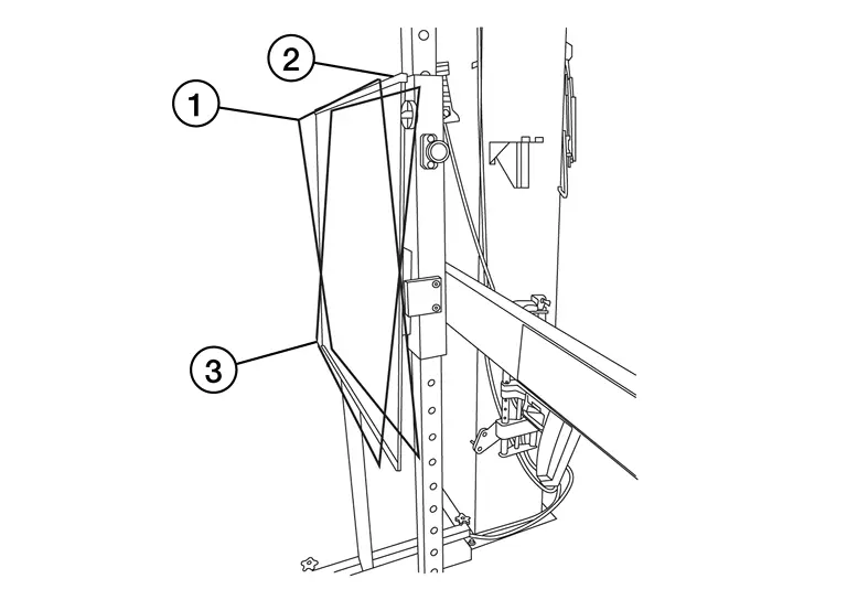
- : Position 1, with top tilted 2° toward vehicle (Not used).
- : Position 2, vertical.
- : Position 3, with top tilted 2° away from vehicle (Not used).
Hunter self-centering wheel adapter
[shown with laser assembly installed] (Hunter alignment rack head may be substituted). 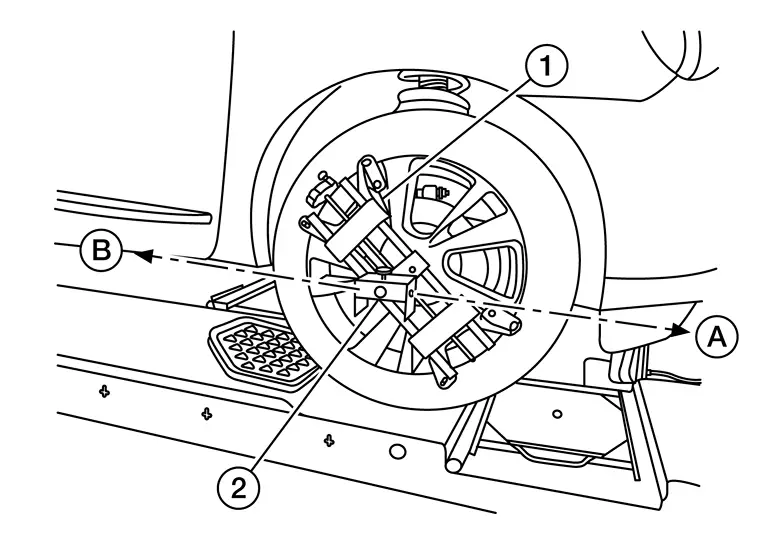 NOTE:
NOTE:Directional arrows
and  are shown to illustrate the direction of the laser assembly beams.
Laser assembly (with bi-directional laser beam) as shown in the illustration.
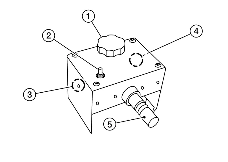
Tightening knob
Power ON/OFF button
Front laser beam opening
Rear laser beam opening

Attaching shaft

Rear stand as shown in the illustration.
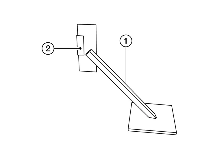
Rear stand
Laser signal reception plate
Distance chain (not shown)
Preparation
ADVANCE PREPARATION FOR RADAR ALIGNMENT PROCEDURE
Adjust all tire pressure to the specified value.
Empty the vehicle. (Remove any luggage from the passenger compartment, luggage room, etc.)
Set shift position to “P” position, and release the parking brake.
Fully fill the fuel tank, and then check that the coolant and oils are filled up to correct level.
Clean the distance sensor area
of the front bumper.
Refer to Vehicle Set Up.
Vehicle Set Up
Accurate adjustment of the radar alignment requires that the target board, wheel adapter, laser assembly, and rear stand be properly positioned.
CAUTION:
If the radar alignment is adjusted with the target board, wheel adapter, laser assembly, or rear stand in the incorrect position, the AEB/I-FCW systems will not function properly or the alignment procedure may not be completed successfully.
PREPOSITION TARGET BOARD
NOTE:
To identify the sensor wave axis center, measure the point
as shown in the illustration.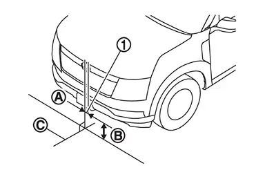
A : 0 mm (0 in) B : 643.6 mm (25.33 in) C : Vehicle center Target board setting must be in the center position. (Position 2)
Attaching the distance sensor alignment kit attachment board to the target board.
Position the target board in front facing the right front side of the vehicle:
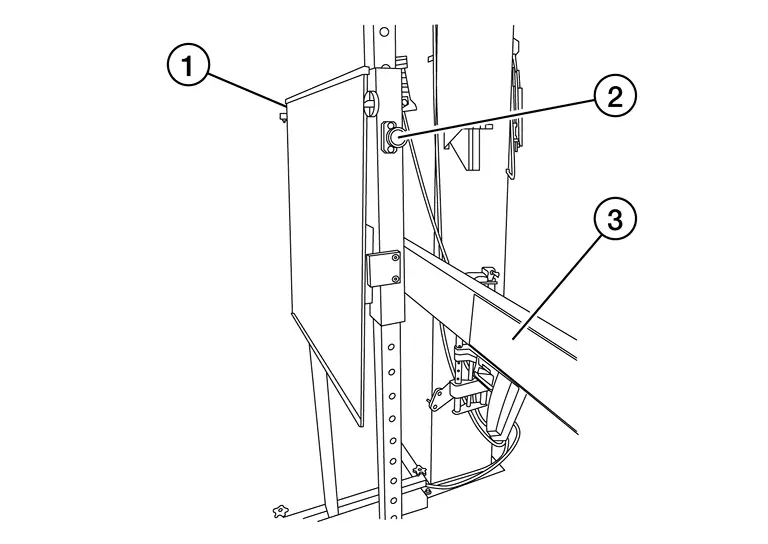
Place the marked center of the target board
813.6 mm (32.03 in) ± 50 mm (1.97 in) facing the distance sensor. Adjust the height of the target board using the adjustable nut
to achieve the proper height. The up/down tolerance is ± 30 mm (1.18 in). Adjust the target board lateral position aligning the marked center of the board horizontally with the center of the distance sensor. The right/left tolerance is ± 80 mm (3.15 in).
Extend the machined arm of the target board exposing the reflective surface
to the right front side of the vehicle.Place one side of the laser assembly
flush against the center of the target board to assist in the positioning.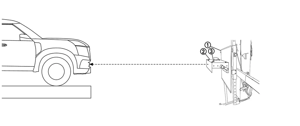
Turn the laser assembly ON
allowing the laser beam to emit through the opening of the laser assembly toward the center of the distance sensor.Move the target board
as necessary so that center of target board aligns with center of distance sensor.Turn the laser assembly OFF when done.
Are using Hunter alignment equipment?
YES>>Refer to Hunter’s equipment instructions for complete vehicle set up and target board setting. Then, refer to Distance Sensor Adjustment.
NO>>GO TO 2.
INSTALLING LASER ASSEMBLY
NOTE:
Insure the steering wheel is positioned in the center straight forward position.
Insure all 4 vehicle wheels do not contain any physical damage.
Install the wheel adapter
on the right front wheel.Mount the laser assembly
to the wheel adapter as shown in the figure.NOTE:When the ignition switch is turned ON, the front laser signal
will be emitted toward the front target board, and the rear laser signal will be emitted toward the rear of the vehicle.
GO TO 3.
SETTING UP REAR STAND
Place the rear stand next to the right rear tire as shown in the figure.
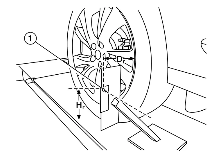
Turn the laser assembly ON allowing the laser beam to be emitted through the front and rear laser assembly openings.
Measure and record the distance (Dr) between the edge of the right rear wheel and the laser beam
on the rear stand (horizontal line).Measure and record the height (Hr) between the laser beam
on the rear stand and ground level (vertical line).Measure and record the distance (Df) between the edge of the right front wheel and the laser beam signal/opening
on the laser assembly (horizontal line).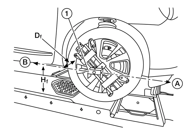
Measure and record the height (Hf) between the laser beam signal/opening
on the laser assembly and ground level (vertical line).NOTE:Horizontal adjustment [front distance (Df) and rear distance (Dr)] is accomplished by slowly turning the steering wheel until the 2 distances are the same.
Vertical adjustment [front height (Hf) and rear height (Hr)] is accomplished by rotating the laser assembly around its axis until the two heights are the same.
Directional arrows
and are shown to illustrate the direction of the laser assembly beams.
Adjust laser beam as necessary until the two distances match and the two heights match.
NOTE:Must be verify both horizontal and vertical adjustments anytime one adjustment is made.
Refer to Setting The Target Board.
Setting The Target Board
Accurate adjustment of the radar alignment requires that the target board be accurately positioned.
CAUTION:
If the radar alignment is adjusted with the target board in the incorrect position, the AEB/I-FCW systems will not function properly or the alignment procedure may not be completed successfully.
TARGET BOARD FINAL SETTING
With the target board arm extended, the laser beam
emitted by the laser assembly will be reflected back toward the laser assembly.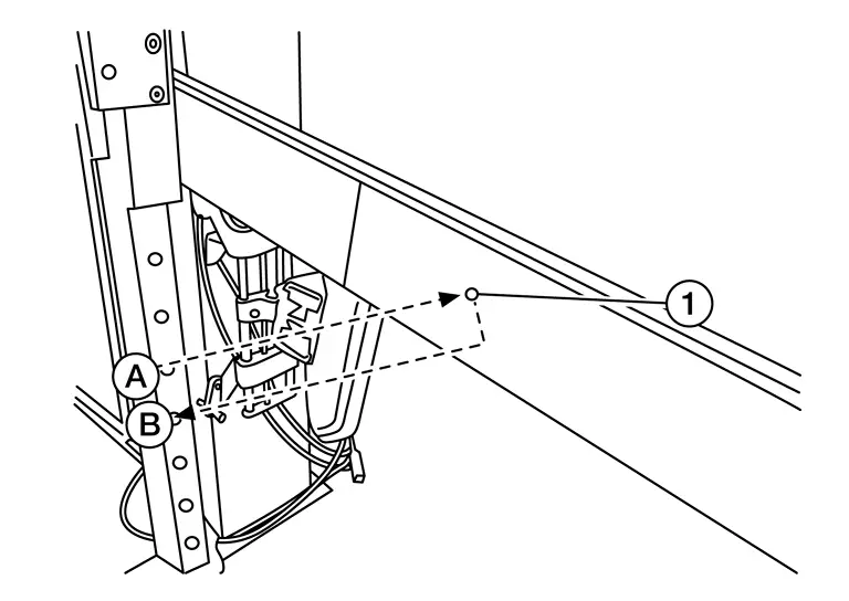 NOTE:
NOTE:When adjusted properly, reflected laser beam
must align with emitted laser beam and the two laser beams will be seen as one.Rotate the target board to achieve the necessary horizontal adjustment.
Adjust the target board leveling screws to achieve the necessary vertical adjustment.
The figure shown illustrates the laser beam
emitted by the laser assembly and its reflection off of the target board arm.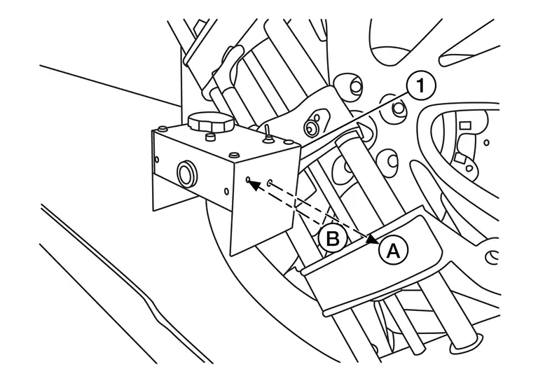
GO TO 2.
CHECK THE POSITION OF THE TARGET BOARD
Do not place anything other than the target board in the space shown in front of the vehicle (view from top).
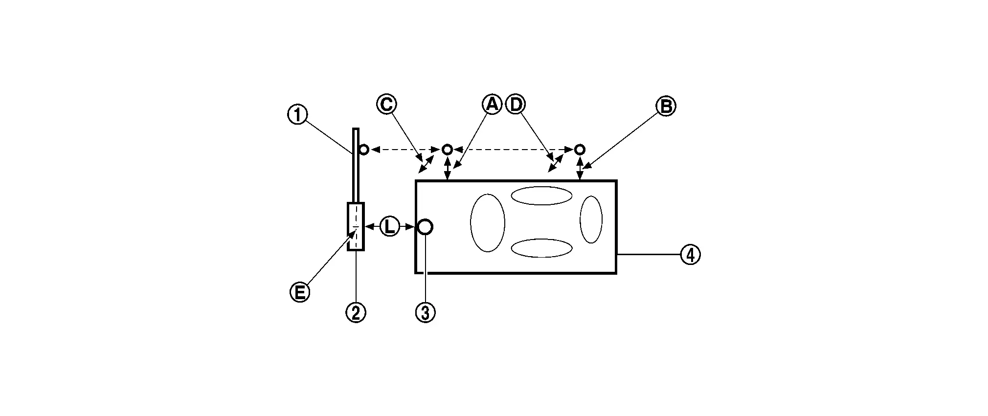
| Target board arm | | Target board | | Distance sensor |
| Vehicle | ||||
| Distance between front wheel and laser beam (Df) | | Distance between rear wheel and laser beam (Dr) |  | Height between front laser beam and ground (Hf) |
 | Height between rear laser beam and ground (Hr) |  | Target board center position |  | 1010 - 1110 mm (39.76 - 43.7 in) |
Refer to Distance Sensor Adjustment.
Distance Sensor Adjustment
The radar alignment is performed automatically with CONSULT.
CAUTION:
Perform all necessary work for radar alignment until the adjustment completes as shown in the procedure. If the procedure does not complete, the AEB/ProPILOT Assist/I-FCW systems are inoperable.
PERFORM RADAR ALIGNMENT
Start the engine.
Connect CONSULT and select “Work support” of “LASER/RADAR”.
Select “MILLIWAVE RADAR ADJUST”.
NOTE:Confirm the following items;
The target should be accurately placed.
The vehicle should be stopped.
Select “Start” after the conditions displayed on CONSULT are satisfied.
CAUTION:
Never select “Start” when the target is not accurately placed.
Select “Next” after the “Radar alignment conditions are ready.” screen is displayed.
NOTE:If the radar is in alignment at this time, “In progress” is displayed. It may take several 10s of seconds until the result is displayed.
Confirm the displayed item.
“Completed.”: Go to 7.
Except “Completed.”: Perform the following services.
Displayed item Possible cause Service procedure Alignment result is over threshold. DTC is detected
The position of the target board is incorrect
Vehicle is moving
Check the vehicle alignment condition and perform radar alignment again Horizontal value is over threshold.
Check the condition.
Perform the adjust again.DTC is detected
The position of the target board is shifted horizontally
Vehicle is moving
Check the vehicle alignment condition and perform radar alignment again Vertical value is over threshold.
Check the condition.
Perform the adjust again.DTC is detected
The position of the target board is shifted vertically
Vehicle is moving
Check the vehicle alignment condition and perform radar alignment again Horizontal value and Vertical value are over threshold.
Check the condition.
Perform the adjust again.DTC is detected
The position of the target board is shifted horizontally and vertically
Vehicle is moving
Check the vehicle alignment condition and perform radar alignment again This display direction is looking from driver seat side. NOTE:This is not an error message, so service procedures are not required.
Target is not detected. (Reflection radio waves is weak.)
Reconfirm the placing condition, and then re-perform adjustment.A target is not-yet -placed
The position of the target board is incorrect
The position of the distance sensor is incorrect
Check the vehicle alignment condition and perform radar alignment again Target setting is offset in horizontal direction.
Reconfirm the placing condition. And then re-perform adjustment or re-install the radar.The position of the target board is shifted horizontally
The position of the distance sensor is shifted horizontally
Check the vehicle alignment condition and perform radar alignment again Target setting is offset in vertical direction.
Reconfirm the placing condition. And then re-perform adjustment or re-install the radar.The position of the target board is shifted vertically
The position of the distance sensor is shifted vertically
Check the vehicle alignment condition and perform radar alignment again EEPROM writing is error.
Re-perform adjustment or replace the ECU.The condition of the alignment is incorrect
Distance sensor malfunction
Check the vehicle alignment condition and perform radar alignment again
If same massage displays again, replace the distance sensor
Hardware is imperfect.
Replace the ECU.Distance sensor hardware has trouble for alignment Replace the distance sensor Signal of vehicle side is imperfect or combination of ECU is incorrect.
Diagnose the other ECU.Other ECU except distance sensor have trouble for alignment Check if any DTC is detected in “Self Diagnostic Result” of other ECU except distance sensor
If any DTC is not detected, replace the distance sensor
Software is incorrect.
Replace the ECU.Distance sensor software is incorrect Replace the distance sensor
Confirm displayed value.
Displayed item Monitor item Reference value Completed Vertical Angle Radar angle “DownW” or “UpW” Vertical Angle Radar measurement result (- 2.50) - (+ 3.00) Horizontal Angle Radar angle “LeftW” or “RightW” Horizontal Angle Radar measurement result Less than 0 ± 4.00 deg Alignment status Alignment complete Within reference value: Go to 8.
Outside of reference value: Check the target board condition and perform radar alignment again.
NOTE:Check the condition of the distance sensor installation.
Check the vehicle for damage.
Replace distance sensor if it is outside the reference value, even when distance sensor installation is installed normally and the vehicle is not damaged.
Select “End”.
CAUTION:
Once “MILLIWAVE RADAR ADJUST” is started with CONSULT, always continue the work until the horizontal radar alignment is completed successfully. If the job is stopped midway, the radar alignment is not adjusted and the AEB/ProPILOT Assist/I-FCW systems cannot operate.
RADAR ALIGNMENT END


Other materials:
Removal and Installation
CAUTION:
Never damage the body panel.
REMOVAL
CAUTION:
Remove luggage side lower finisher. Refer to Removal and Installation.
Apply protective tape (A) on rear pillar finisher to protect it from damage.
Disengage seat belt finisher fixing pawls using a remover tool (A).
: Pawl
Apply protectiv ...
Precautions for Removing Battery Terminal
NOTE:
NOTE:
NOTE:
The removal of 12V battery may cause a DTC detection error.
HOW TO DISCONNECT 12V BATTERY TERMINAL
Disconnect 12V battery terminal according to instruction described below.
Open the hood.
Turn ignition switch to the ON position.
Turn ignition switch to the OFF position with the d ...
Removal and Installation
WARNING:
REMOVAL
Disconnect battery cable from negative terminal. Refer to Removal and Installation.
Remove engine under cover rear. Refer to Removal and Installation.
Remove front cross member. Refer to Removal and Installation.
Remove starter motor cover 2 mounting bolts , and then remove starter ...

0.0089