
Nissan Armada 2025-2026 Service and Repair Manual: Cut and Butt Joint Weld
Damages that are considered difficult to repair by frame straightening work, such as a deformed crash horn, may be restored by a butt joint weld only if the Service Manual and/or the Body Repair Manual instructs so.
As an example, the butt joint weld procedure for A60 is outlined below.
(1) CRASH HORN (Partial replacement)
(Work after 1st crossmember has been removed.)
Service Joint
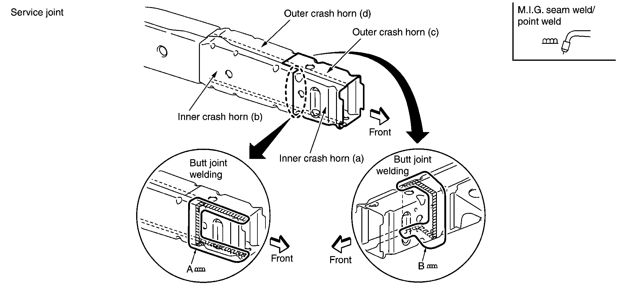
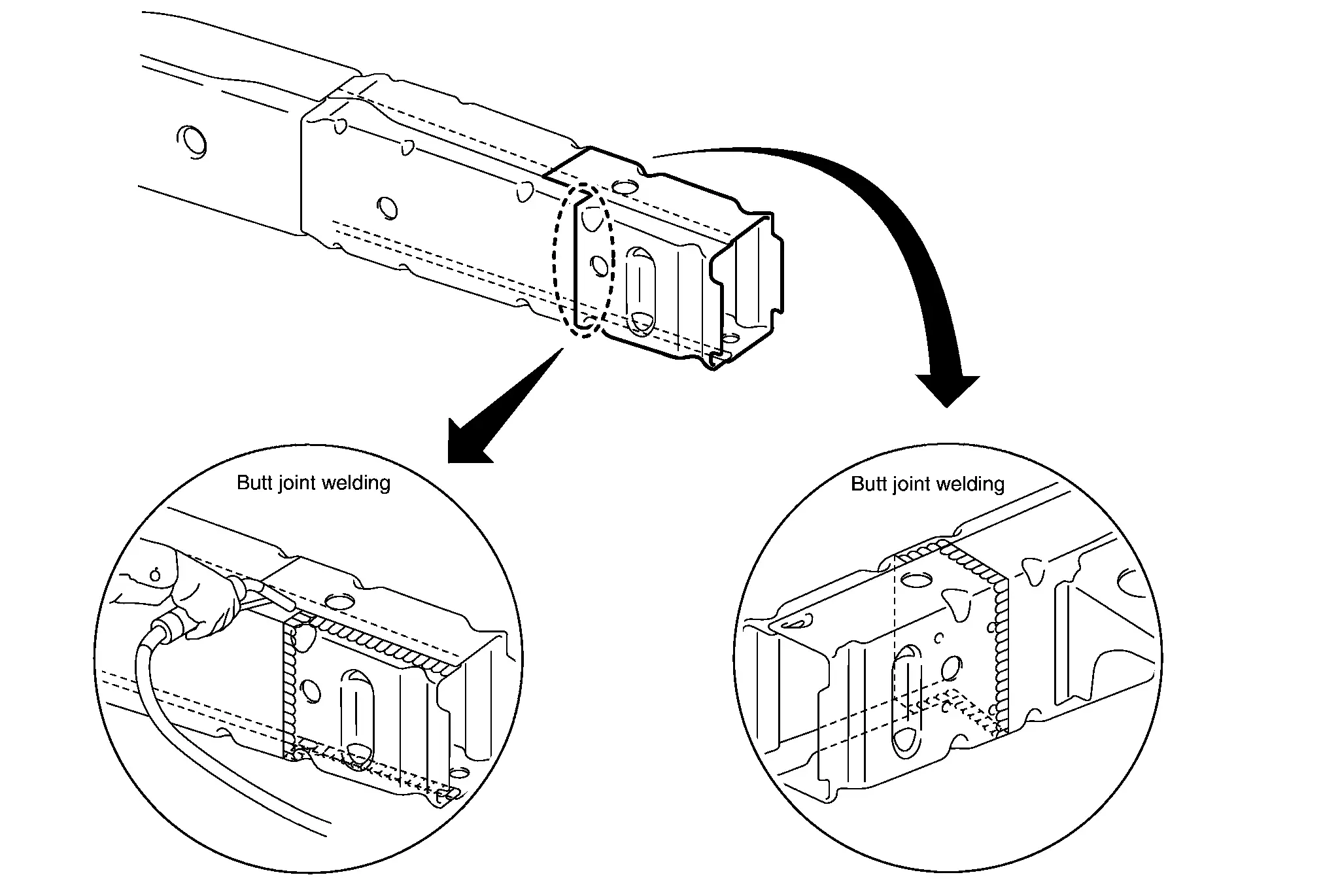
Portions to be welded:
A: Inner side rail crash horn (a), inner side rail crash horn (b) and outer side rail crash horn (c)
B: Outer side rail crash horn (c), outer side rail crash horn (d) and inner side rail crash horn (b)
(2) REMOVAL
(a) Scribe a straight line on the outer side rail crash horn and inner side rail crash horn along the hole center as shown in the figure.
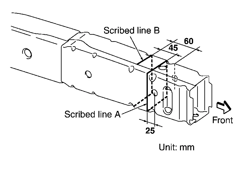
(b) Cut off the outer side rail crash horn and inner side rail crash horn along scribed line (A). Do not cut on the hole.
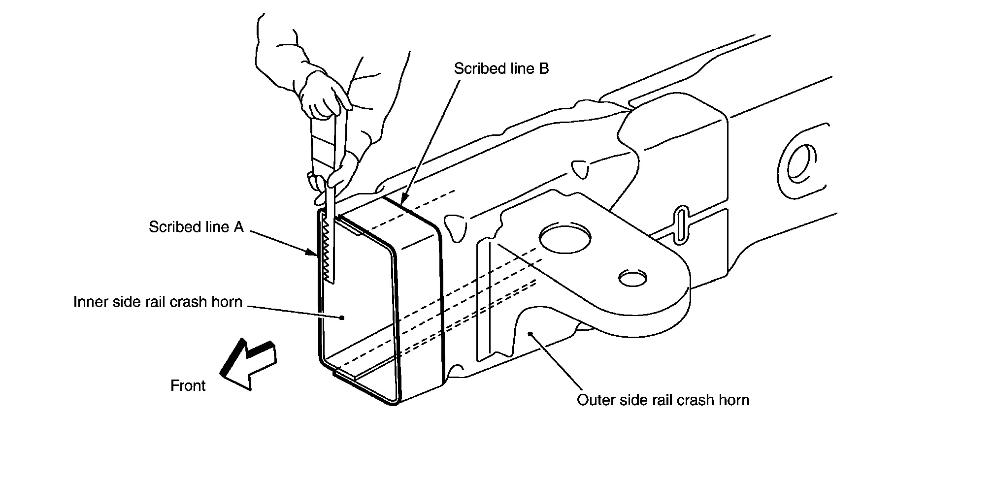
(c) Cut the inner side rail crash horn at 45 mm (1.77 in) backward from cut position of cut line (A) [along line (B)].
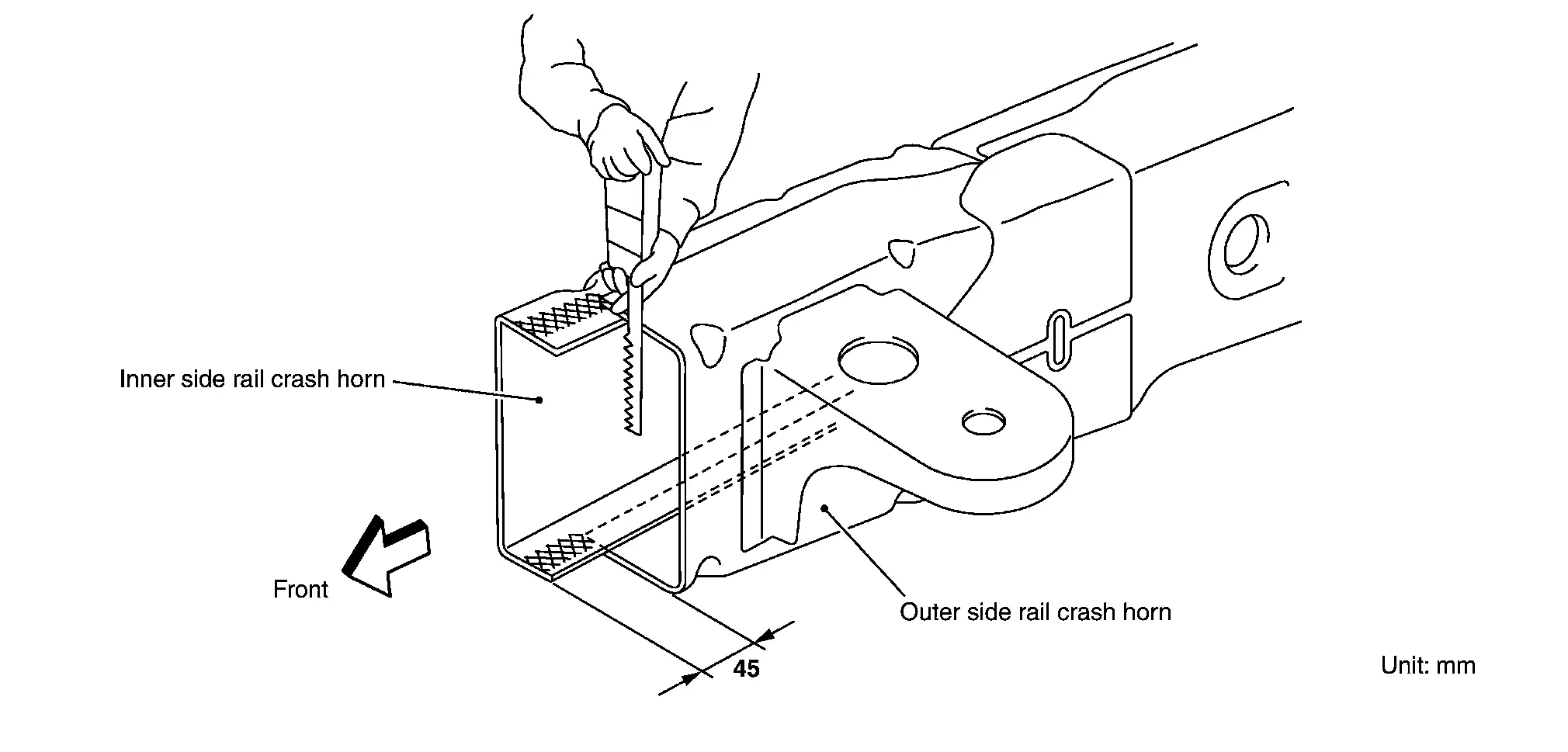
After removing the outer panel, dress the area on the inner panel surface with a sander or equivalent.
(3) INSTALLATION
(a) Scribe a straight line on the inner side rail crash horn along the hole center as shown in the figure.
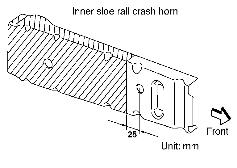
Cut off the inner side rail crash horn along the scribed line.
(b) Scribe a straight line on the outer side rail crash horn along the hole center as shown in the figure.
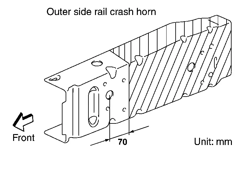
Cut off the outer side rail crash horn along the scribed line.
(c) Weld part to be butt joint welded and seam-welded corner to corner as shown in the figure.
(4) PRECAUTIONS FOR WELDING
(a) When tack welding is finished, always verify that the crash horn is assembled in the proper dimensions before starting final welding.
(b) Before starting welding work, always remove the components around the weld points. If it is difficult to remove the components, cover them with a fireproof sheet to avoid attachment of any weld spatters and subsequent damage to the surrounding portions.
(c) After painting, spray a sufficient amount of anti-corrosive wax to the rear side of the weld points through the holes near the weld points.
 Precautions for Frame Repair
To eliminate any residual stress from the frame, always perform hammering during straightening work. This is extremely important because residual stress removal is more difficult in frames than in sid ...
 Conclusion
When repairing a frame deformed by a collision, every body repair technician must always keep in mind that the original frame performance of the vehicle (running performance and anti-collision safety) ...
Other materials:
Exploded View
Idler pulley Alternator Drive belt auto-tensioner Crankshaft pulley A/C compressor Water pump Drive belt A/C compressor belt View Indicator Range when new drive belt is installed Possible use range Always replace after every disassembly. ...
Removal and Installation
REMOVAL
Remove back door inner finisher. Refer to Removal and Installation.
Disconnect intelligent rear view mirror camera harness connector .
Disengage intelligent rear view mirror camera mounting bolts , and then remove intelligent rear view mirror camera.
INSTALLATION
Install in the reverse o ...
Diagnostic Work Sheet
DESCRIPTION
INTERVIEW SHEET SAMPLE
Interview sheet Customer name MR/MS Registration number Initial year registration Vehicle type VIN Storage date Engine Mileage km ( Mile) Situation where malfunction is occurred Malfunction category â–¡ Unable to brake    □ Unable to releaseâ ...

0.0058