Work Flow
OBTAIN INFORMATION ABOUT SYMPTOM
Refer to Diagnostic Work Sheet and interview the customer to obtain the malfunction information (conditions and environment when the malfunction occurred) as much as possible when the customer brings in the vehicle.
>>
GO TO 2.
CHECK DTC
-
Before checking the malfunction, check whether any DTC exists.
-
If DTC exists, perform the following operations.
-
Record the DTC and freeze frame data. (Print out the data using CONSULT and affix them to the Work Order Sheet.)
-
Erase DTCs.
-
Check the relationship between the cause that is clarified with DTC and the malfunction information described by the customer. Symptom Table is effective.
-
Do malfunction information and DTC exists?
Malfunction information and DTC exists. >>GO TO 3.
Malfunction information exists, but no DTC. >>GO TO 4.
No malfunction information, but DTC exists. >>GO TO 5.
REPRODUCE MALFUNCTION SYMPTOM
Check any malfunction described by a customer, except those with DTC on the vehicle.
Also investigate whether the symptom is a fail-safe or normal operation. Refer to Fail-Safe.
When a malfunction symptom is reproduced, the question sheet is effective. Refer to Diagnostic Work Sheet.
Verify the relationship between the symptom and the conditions in which the malfunction described by the customer occurs.
>>
GO TO 5.
REPRODUCE MALFUNCTION SYMPTOM
Check the malfunction described by the customer on the vehicle.
Also investigate whether the symptom is a fail-safe or normal operation. Refer to Fail-Safe.
When a malfunction symptom is reproduced, the question sheet is effective. Refer to Diagnostic Work Sheet.
Verify the relationship between the symptom and the conditions in which the malfunction described by the customer occurs.
>>
GO TO 6.
PERFORM “DTC CONFIRMATION PROCEDURE”
Perform “DTC CONFIRMATION PROCEDURE” of the appropriate DTC to check if DTC is detected again.
Refer to DTC Inspection Priority Chart when multiple DTCs are detected, and then determine the order for performing the diagnosis.
 NOTE:
NOTE:
If no DTC is detected, refer to the freeze frame data.
Is any DTC detected?
YES>>GO TO 7.
NO>>Check according to Intermittent Incident.
IDENTIFY MALFUNCTIONING SYSTEM WITH “DIAGNOSIS CHART BY SYMPTOM”
Use Symptom Table from the symptom inspection result in step 4. Then identify where to start performing the diagnosis based on possible causes and symptoms.
>>
GO TO 8.
REPAIR OR REPLACE THE MALFUNCTIONING PARTS
Repair or replace the detected malfunctioning parts.
Reconnect parts or connector after repairing or replacing, and then erase DTC if necessary.
>>
GO TO 8.
FINAL CHECK
Perform “DTC CONFIRMATION PROCEDURE” again to make sure that the repair is correctly performed.
Check that malfunctions are not reproduced when obtaining the malfunction information from the customer, referring to the symptom inspection result in step 3 or 4.
Is DTC or malfunction symptom reproduced?
YES-1>>DTC is reproduced: GO TO 5.
YES-2>>Malfunction symptom is reproduced: GO TO 6.
NO>>Before delivering the vehicle to the customer, make sure that DTC is erased.
Diagnostic Work Sheet
DESCRIPTION
There are many operating conditions that may cause a malfunction of the transmission parts. By understanding those conditions properly, a quick and exact diagnosis can be achieved.
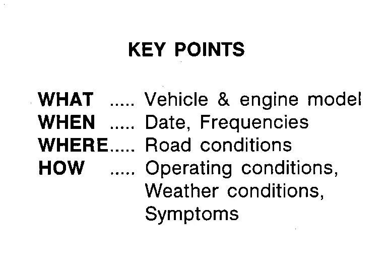
In general, customers have their own criteria for a problem. Therefore, it is important to understand the symptom and status well enough by asking the customer about the concerns carefully. In order to systemize all the information for the diagnosis, prepare the question sheet referring to the question points.
WORKSHEET SAMPLE
| Question Sheet | |||||||
|---|---|---|---|---|---|---|---|
| Customer name MR/MS | Engine # | Manuf. Date | |||||
| Incident Date | VIN | ||||||
| Model & Year | In Service Date | ||||||
| Trans. | Mileage | km/Mile | |||||
| Symptoms | □ vehicle does not move (□ Any position □ Particular position ) | ||||||
| □ No upshift (□ 1GR ⇒ 2GR □ 2GR ⇒ 3GR □ 3GR ⇒ 4GR □ 4GR ⇒ 5GR □ 5GR ⇒ 6GR □ 6GR ⇒ 7GR □ 7GR ⇒ 8GR □ 8GR ⇒ 9GR) | |||||||
| □ No downshift (□ 9GR ⇒ 8GR □ 8GR ⇒ 7GR □ 7GR ⇒ 6GR □ 6GR ⇒ 5GR □ 5GR ⇒ 4GR □ 4GR ⇒ 3GR □ 3GR ⇒ 2GR □ 2GR ⇒ 1GR) | |||||||
| □ Lock-up malfunction | |||||||
| □ Shift point too high or too low | |||||||
| □ Shift shock or slip | |||||||
| □ Noise or vibration | |||||||
| □ No kick down | |||||||
| □ No pattern select | |||||||
| □ Others | |||||||
| Frequency | □ All the time | □ Under certain conditions | □ Sometimes ( times a day) | ||||
| Weather conditions | □ Not affected | ||||||
| Weather | □ Fine | □ Clouding | □ Raining | □ Snowing | □ Other ( ) | ||
| Temp. | □ Hot | □ Warm | □ Cool | □ Cold | □ Temp. Approx. °C/°F | ||
| Humidity | □ High | □ Middle | □ Low | ||||
| Transmission conditions | □ Not affected | ||||||
| □ Cold | □ During warm-up | □ After warm-up | |||||
| □ Engine speed ( rpm) | |||||||
| Road conditions | □ Not affected | ||||||
| □ In town | □ In suburbs | □ Freeway | □ Off road (Up/Down) | ||||
| Driving conditions | □ Not affected | ||||||
| □ At starting | □ While idling | □ While engine racing | □ At racing | □ While cruising | |||
| □ While accelerating | □ While decelerating | □ While turning (Right/Left) | |||||
| □ vehicle speed [ km/h ( MPH)] | |||||||
| Other conditions | |||||||
Other materials
Accelerator Control System. Accelerator Control System
Accelerator Control System
Exploded View
Accelerator pedal assembly
Accelerator pedal bracket
: N·m (kg-m, ft-lb)
: N·m (kg-m, in-lb)
Removal and Installation
REMOVALCAUTION:
Never disassemble accelerator ped ...
Lower Link
Exploded View
Frame
Eccentric disc
Adjusting bolt
Stopper rubber
Lower link
Steering knuckle
: Always replace after every disassembly.
: N·m (kg-m, ft-lb)
Removal and Installation
WARNING:
Jacking up or lift up the vehicle may the vehicle height to go down which cause ...
Side Camera
Removal and Installation
REMOVAL
Remove the door mirror finisher. Refer to Disassembly and Assembly.
Remove the side camera mounting screw , and then remove the side camera .
INSTALLATIONInstall in the reverse order of removal.
Perform parameter writing. (With ProPILOT Assist 2.1) Refer to Work ...