Exploded View
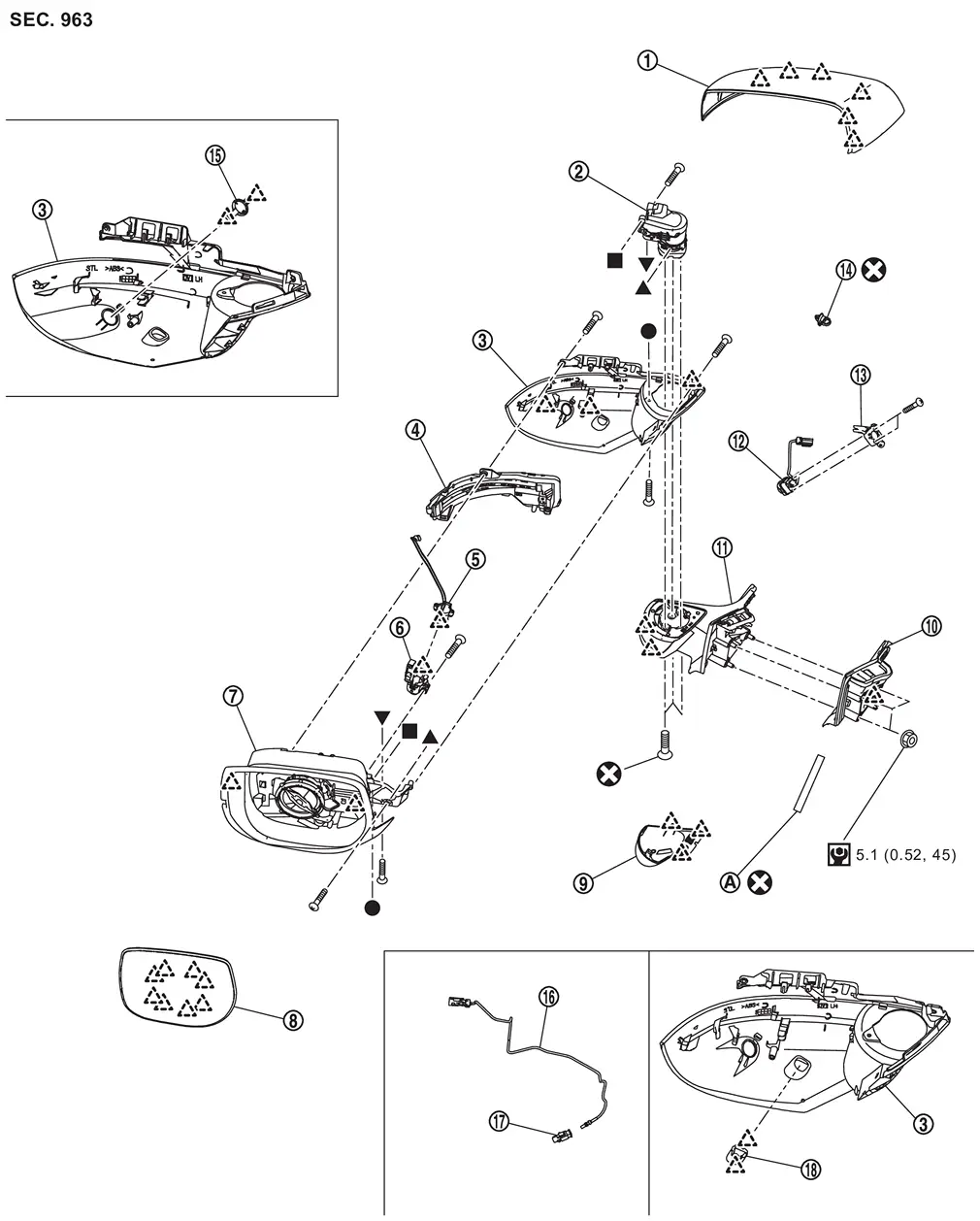
 |
Door mirror cover |  |
Power folding motor |  |
Door mirror finisher |
 |
Side turn signal lamp |  |
Puddle lamp bracket (with puddle lamp) |  |
Puddle lamp (with puddle lamp) |
 |
Door mirror housing assembly |  |
Glass mirror |  |
Door mirror base cover |
 |
Door mirror base gasket |  |
Door mirror base assembly |  |
Side camera (with side camera) |
 |
Side camera bracket (with side camera) |  |
Harness clip |  |
Side camera cover (without side camera) |
 |
Side camera harness B (with side camera) |  |
Side camera harness A (with side camera) |  |
Puddle lamp cover (without puddle lamp) |
 |
Vinyl tape | ||||
 |
: Pawl | ||||
 |
: Always replace after every disassembly. | ||||
 |
: N·m (kg-m, in-lb) | ||||
 , , , ,  , ,  : Indicates that the part is connected at points with same symbol in actual vehicle. : Indicates that the part is connected at points with same symbol in actual vehicle. |
|||||
Door Mirror Assembly
Removal and Installation
REMOVAL
CAUTION:
Never damage the front door panel and any parts.
Remove front door sash inner cover. Refer to Removal & Installation.
Disconnect door mirror assembly harness connectors and  .
.
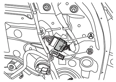
 NOTE:
NOTE:
Harness connector : Side camera harness connector (with side camera)
Remove harness clip.
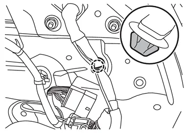
 |
: Clip |
Remove door mirror assembly mounting nuts .
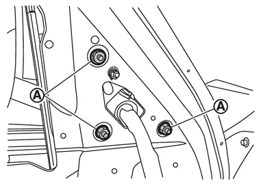
Disengage door mirror assembly fixing pawl , and then remove door mirror assembly.
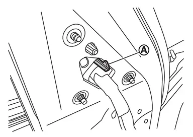
INSTALLATION
Note the following items, and then install in the reverse order of removal.
CAUTION:
-
In accordance with the replacement operation of the door mirror assembly and side camera, the parameter writing of the camera and the camera image calibration must be performed.
-
Refer to the matrix below and perform the action as appropriate.
-
The numbers in the matrix indicate the operating procedure.
| Situations | |||||
|---|---|---|---|---|---|
| Operations | Replace door mirror assembly & side camera | Replace door mirror assembly (side camera reused) | Replace side camera (door mirror assembly reused) | Remove door mirror assembly with camera | |
| Parameter writing for camera | 1 | - | 1 | - | Refer to Work Procedure |
| Camera image calibration | 2 | 1 | 2 | 1 | Refer to Work Procedure |
Disassembly and Assembly
DISASSEMBLY
Remove door mirror assembly. Refer to Removal and Installation.
Remove door mirror cover. Refer to Removal and Installation.
Disconnect all terminals from harness connector .
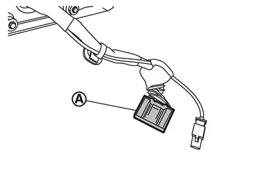
NOTE:
Make a mark (short note, photo, etc.) of terminals layout, before disassembly.
Remove harness clip and vinyl tape .
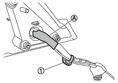
Remove door mirror base gasket.
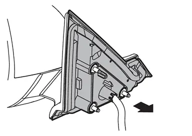
Disengage door mirror base cover fixing pawls, and then remove door mirror base cover.
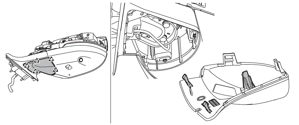
|
: Pawl |
Remove door mirror base assembly fixing screws , and then remove door mirror base assembly.
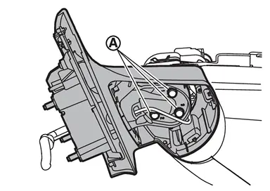
Remove door mirror finisher fixing screws .
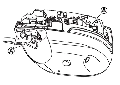
Disengage door mirror finisher fixing pawls, and then remove door mirror finisher from door mirror housing assembly.
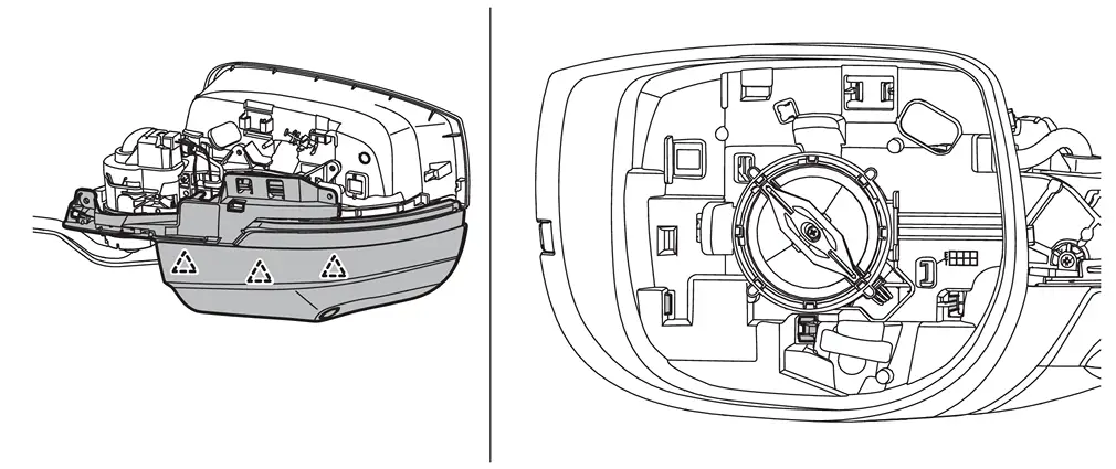
|
: Pawl |
Remove side camera (with side camera) or side camera cover (without side camera). Refer to the follows.
-
Side camera: Removal and Installation.
-
Side camera cover: Remove side camera cover fixing pawls, and then remove side camera cover.
Remove side turn signal lamp. Refer to Removal & Installation.
Remove puddle lamp (with puddle lamp) or puddle lamp cover (without puddle lamp). Refer to the follows.
-
Puddle lamp: Removal and Installation.
-
Puddle lamp cover: Remove puddle lamp cover fixing pawls, and then remove puddle lamp cover.
Disconnect harness connector .
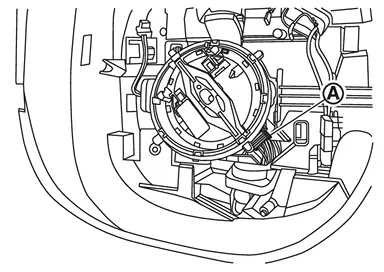
Remove power folding motor fixing screws , and then remove power folding motor.
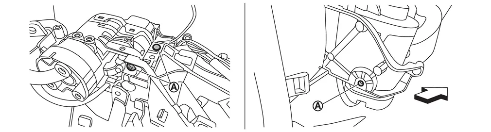
| : vehicle front |
Remove harness from power folding motor.
NOTE:
Make a mark (short note, photo, etc.) of harness layout, before removal.
Disconnect side camera harness A and side camera harness B (with side camera).
ASSEMBLY
Note the following items, and then assemble in the reverse order of disassembly.
CAUTION:
-
Never reuse door mirror base assembly fixing screws, vinyl tape, and harness clip. Always replace it with a new one when it is removed.
-
After installation, visually check that fixing pawls are securely engage.
Glass Mirror
Removal and Installation
REMOVAL
Place glass mirror upward.
Apply protective tapes (A) on the part to protect it from damage.
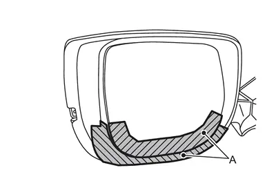
Insert remover tool (A) into the recess at between glass mirror and door mirror actuator, and then disengage glass mirror fixing pawls.
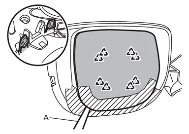
CAUTION:
Disengage the fixing pawls slowly so they are not damaged.
|
: Pawl |
Disconnect BSW harness connector .
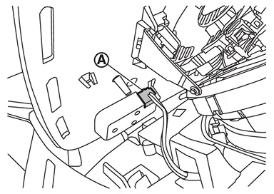
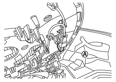
Disconnect auto anti-dazzling harness connector (if equipped).
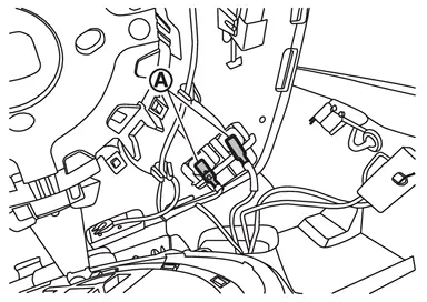
Disconnect door mirror heater harness connectors (if equipped).
Remove glass mirror.
INSTALLATION
Note the following item, and then install in the reverse order of removal.
CAUTION:
After installation, visually check that fixing pawls are securely engaged.
Door Mirror Cover
Removal and Installation
REMOVAL
Remove glass mirror. Refer to Removal and Installation.
Apply protective tapes (A) on the part to protect it from damage.
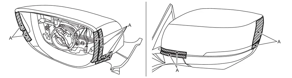
Disengage door mirror cover fixing pawls from door mirror housing assembly .
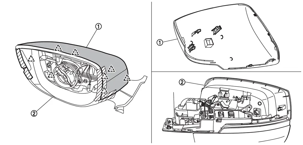
|
: Pawl |
Remove door mirror cover.
INSTALLATION
Note the following item, and then install in the reverse order of removal.
CAUTION:
After installation, visually check that fixing pawls are securely engaged.
Other materials
Warning/indicator lights (other)
Automatic brake hold indicator light (white)
In the Nissan Armada, the white automatic brake hold indicator light confirms
that the system is activated and currently in standby mode, ready to assist the
driver when needed. This feature enhances comfort during stop-and-go driving by
mainta ...
Precautions for Pop up Engine Hood
PRECAUTIONS FOR POP UP ENGINE HOOD : Precautions
WARNING:
Always observe the following items for preventing accidental activation.
Before removal or installation of the pop-up engine hood and harness, always OFF the ignition switch, disconnect the battery negative terminal, and wait for 3 minutes ...
Driver Monitor Camera Control Unit
Exploded View
Driver monitor camera control unit
: N·m (kg-m, in-lb)
Removal and Installation
REMOVALRemove the front speaker grille. Refer to Removal and Installation.
Remove the mounting nuts, and remove the driver monitor camera control unit.
Disconnect the d ...