Exploded View
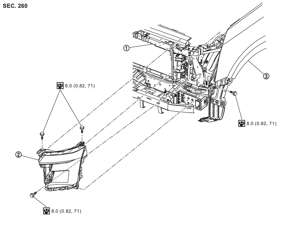
 |
Radiator core support |  |
Front combination lamp |  |
Front fender assembly |
 |
: N·m (kg-m, in-lb) | ||||
Removal and Installation
CAUTION:
Disconnect the battery negative terminal or remove power circuit fuse when performing the operation for preventing electric leakage. Refer to Precautions for Removing Battery Terminal.
REMOVAL
Remove front bumper fascia. Refer to following.
-
City model: Removal and Installation.
-
Off road model: Removal and Installation.
Remove front combination lamp mounting bolts.
Pull out front combination lamp forward the vehicle.
Disconnect front combination lamp harness connectors, and then remove front combination lamp.
INSTALLATION
Note the following item, and then install in the reverse order of removal.
CAUTION:
After installation, perform aiming adjustment. Refer to Adjustment.
Replacement
CAUTION:
Disconnect the battery negative terminal or remove power circuit fuse when performing the operation for preventing electric leakage. Refer to Precautions for Removing Battery Terminal.
HEADLAMP (Hi)
CAUTION:
Replacement of a single part is not possible due to the adoption of LED. For replacement, replace front combination lamp as a set. Refer to Removal and Installation.
HEADLAMP (Lo)
CAUTION:
Replacement of a single part is not possible due to the adoption of LED. For replacement, replace front combination lamp as a set. Refer to Removal and Installation.
PARKING LAMP
CAUTION:
Replacement of a single part is not possible due to the adoption of LED. For replacement, replace front combination lamp as a set. Refer to Removal and Installation.
DAYTIME RUNNING LIGHT
CAUTION:
Replacement of a single part is not possible due to the adoption of LED. For replacement, replace front combination lamp as a set. Refer to Removal and Installation.
FRONT TURN SIGNAL LAMP
CAUTION:
Replacement of a single part is not possible due to the adoption of LED. For replacement, replace front combination lamp as a set. Refer to Removal and Installation.
FRONT SIDE MARKER LAMP
CAUTION:
Replacement of a single part is not possible due to the adoption of LED. For replacement, replace front combination lamp as a set. Refer to Removal and Installation.
Other materials
Hood
Exploded View
Hood assembly
Hood hinge RH
Stud ball
Hood stay RH
Hood seal
Hood bumper rubber 1
Hood bumper rubber 2
Radiator core seal
Hood insulator
Hood stay LH
Hood hinge LH
: Clip
: Pawl
: Body grease
, : Indicates that the part is connected at poi ...
System Initialization
Description
If any of the following operations are performed, the initialization is necessary for normal operation of power window system. Refer to Work Procedure.
When each power window motor replaced.
Power supply to the each power window motor is not cut off properly.
Removal and installatio ...
Additional Service When Replacing Driving Video Recorder Control Module
Work Procedure
DRIVING VIDEO RECORDER CONTROL MODULE REPLACEMENT
Replace driving video recorder control module. Refer to Removal and Installation.
>>
GO TO 2.
WRITING OF VIN DATA TO DRIVING VIDEO RECORDER CONTROL MODULE
With CONSULT
Ignition switch ON and wait at least 5 seconds.
Select ...