Brake Pad
Inspection and Adjustment
WARNING:
-
Jacking up or lift up the vehicle may the vehicle height to go down which cause a personal injury and/or damage to the air suspension component parts. Refer to Precaution for when Jacking and Lifting Up the vehicle with Electronic Air Suspension System.
INSPECTION
Check brake pad wear thickness from an inspection hole on cylinder body. Check using a scale if necessary.
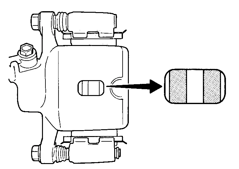
| Wear thickness | : Refer to Front Disc Brake. |
ADJUSTMENT
Burnish contact surfaces between disc rotor and brake pads according to the following procedure after refinishing or replacing brake pads, or if a soft pedal occurs at very low mileage.
CAUTION:
-
Be careful of vehicle speed because the brake does not operate firmly/securely until pads and disc rotor are securely fitted.
-
Only perform this procedure under safe road and traffic conditions. Use extreme caution.
Drive vehicle on straight, flat road.
Depress brake pedal with the power to stop vehicle within 3 to 5 seconds until the vehicle stops.
Drive without depressing brake for a few minutes to cool the brake.
Repeat steps 1 to 3 until pad and disc rotor are securely fitted.
Disc Rotor
Inspection and Adjustment
WARNING:
-
Jacking up or lift up the vehicle may the vehicle height to go down which cause a personal injury and/or damage to the air suspension component parts. Refer to Precaution for when Jacking and Lifting Up the vehicle with Electronic Air Suspension System.
INSPECTION
Appearance
Check surface of disc rotor for uneven wear, cracks, and serious damage. Replace it if necessary.
-
2WD: Refer to Removal and Installation.
-
4WD: Refer to Removal and Installation.
Runout
Fix the disc rotor to the wheel hub and bearing assembly with wheel nuts (2 points at least).
Check the wheel bearing axial end play.
-
2WD: Refer to Inspection.
-
4WD: Refer to Inspection.
Inspect the runout with a dial indicator to measure at 10 mm (0.39 in) inside the disc edge.
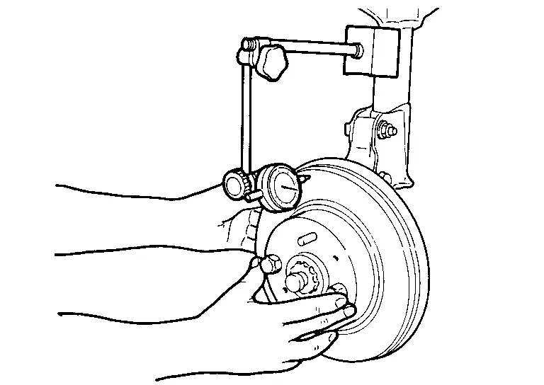
| Runout (with it attached to the vehicle) | : Refer to Front Disc Brake. |
Find the installation position that has a minimum runout by shifting the disc rotor-to-wheel hub and bearing assembly installation position by one hole at a time if the runout exceeds the limit value.
Refinish the disc rotor if the runout is outside the limit even after performing the above operation.
CAUTION:
-
Check in advance that the thickness of the disc rotor is wear thickness + 0.3 mm (0.012 in) or more.
-
If the thickness is less than wear thickness + 0.3 mm (0.012 in), replace the disc rotor.
-
2WD: Refer to Removal and Installation.
-
4WD: Refer to Removal and Installation.
-
| Wear thickness | : Refer to Front Disc Brake. |
Thickness
Check the thickness of the disc rotor using a micrometer. Replace the disc rotor if the thickness is below the wear limit.
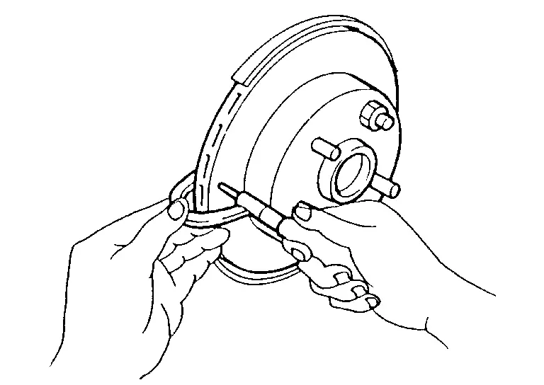
-
2WD: Refer to Removal and Installation.
-
4WD: Refer to Removal and Installation.
| Wear thickness | : Refer to Front Disc Brake. |
ADJUSTMENT
Burnish contact surfaces between disc rotors and brake pads according to the following procedure after refinishing or replacing disc rotor, or if a soft pedal occurs at very low mileage.
CAUTION:
-
Be careful of vehicle speed because the brake does not operate firmly/securely until pad and disc rotor are securely fitted.
-
Only perform this procedure under safe road and traffic conditions. Use extreme caution.
Drive vehicle on straight, flat road.
Depress brake pedal with the power to stop vehicle within 3 to 5 seconds until the vehicle stops.
Drive without depressing brake for a few minutes to cool the brake.
Repeat steps 1 to 3 until pad and disc rotor are securely fitted.
Front Disc Brake
Unit: mm (in)
| Item | Limit | |
|---|---|---|
| Brake pad | Wear thickness | 2.0 (0.079) |
| Disc rotor | Wear thickness | 27.4 (1.079) |
| Thickness variation (measured at 8 positions)* | 0.006 (0.0002) | |
| Runout (with it attached to the vehicle) | 0.035 (0.0014) | |
*To check if rotor imbalance, rotor runout or rotor deformation is occurred.
Other materials
Noise, Vibration and Harshness (nvh) Troubleshooting
NVH Troubleshooting Chart
Use the chart below to find the cause of the symptom. The numbers indicate the order of the inspection. If necessary, repair or replace these parts.
SUSPECTED PARTS
(Possible cause) Symptom Reference
Transfer fluid leakage Noise
TRANSFER FLUID (Level low)
1 ...
Automatic Back Door Close Switch Assembly
Removal and Installation
REMOVALRemove automatic back door switch finisher. Refer to Removal and Installation.
Disengage automatic back door close switch assembly fixing pawls using a remover tool (A), and then remove automatic back door close switch assembly from automatic back door switch finishe ...
Front Grille
Off Road Models
Exploded View
Front bumper fascia
Grommet
Front grille upper
Front grille
Front emblem
Front camera
: Clip
: Pawl
: Indicate that the part is connected at points with same symbol in actual vehicle.
Removal and Installation
REMOVALFully open hood assemb ...