Removal and Installation
REMOVAL
CAUTION:
Before removing, take a short memo/photo to remember door harness and cable layout.
Remove front door glass. Refer to Removal and Installation.
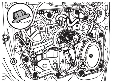
Disconnect harness connectors  , and then disengage harnesses fixing clips.
 |
: Clip |
Remove hole seals  from front door panel, and then remove front door module assembly mounting bolts from service holes.
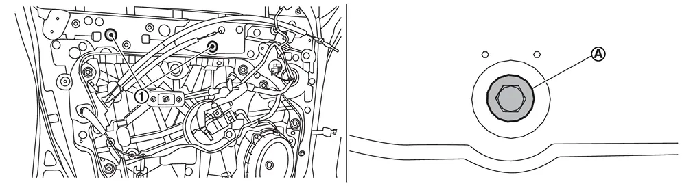
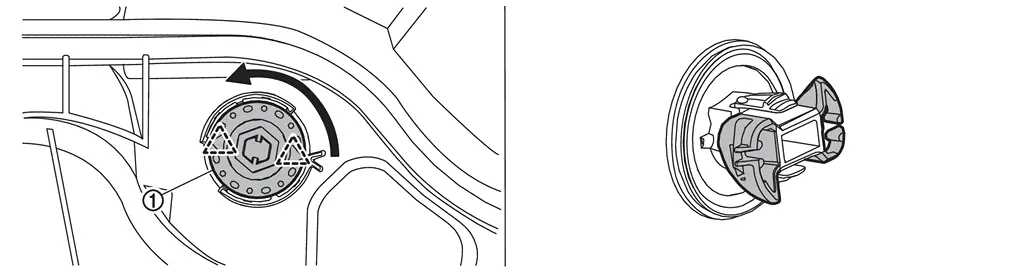
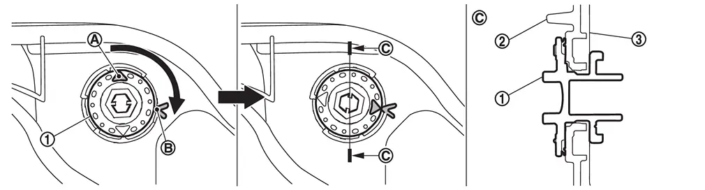
Remove front door regulator fasteners.Turn front door regulator fastener counterclockwise to disengage fixing pawls.
 |
: Pawl |
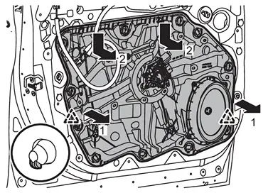
Disengage fixing pawls, and then remove front door module assembly according to numerical order 1→2 indicated by arrows as shown in the figure.
|
: Pawl |
INSTALLATION
Note the following items, and then install in the reverse order of removal.
CAUTION:
-
When front door regulator fastener
installation, align arrow mark of front door regulator fastener with position mark  of front door module assembly
  .
.

Front door panel -
Never reuse hole seal. Always replace it with a new one when it is removed.
-
After installing, perform the inspection and adjustment. Refer to Inspection and Adjustment.
Disassembly and Assembly
DISASSEMBLY
Remove front door module assembly. Refer to Removal and Installation.
Remove front door power window motor mounting bolts, and then remove front door power window motor.
ASSEMBLY
Note the following item, and then assemble in the reverse order of disassembly.
CAUTION:
After assembly, perform the inspection and adjustment. Refer to Inspection and Adjustment.
Inspection and Adjustment
SYSTEM INITIALIZATION
Perform additional service for operating the power window control system normally after installing front door regulator. Refer to Work Procedure.
FITTING INSPECTION
-
Check that the glass is fitted securely into the sash groove.
-
Lower the glass slightly [approximately 10 to 20 mm (0.39 to 0.79 in)], and check that the clearance to the sash is parallel. Loosen each mounting bolt and fastener to correct the glass position if the clearance between the glass and sash are not parallel.
Other materials
Warning/indicator lights (yellow)
Anti-lock Braking System (ABS) warning light
or
In the Nissan Armada, the Anti-lock Braking System (ABS) warning light is an
essential diagnostic indicator that confirms the proper operation of the braking
assistance system. When the ignition switch is turned to the ON position, this li ...
Vehicle identification
Vehicle Identification Number (VIN) plate
The VIN plate on your Nissan Armada is mounted as shown and serves as the primary
identifier for the vehicle. This number is essential for registration, insurance,
and service records.
Vehicle identification number (chassis number)
The chassis ...
Additional Service When Replacing Steering Column Control Module
Description
Each function is reset to the following condition when the steering column control module is replaced. For details, refer to Work Procedure. Function Condition Procedure
Memory (Steering column)
Erased
Perform memory storing
Work Procedure
REPLACE STEERING COLUMN CONTROL MODUL ...