Exploded View
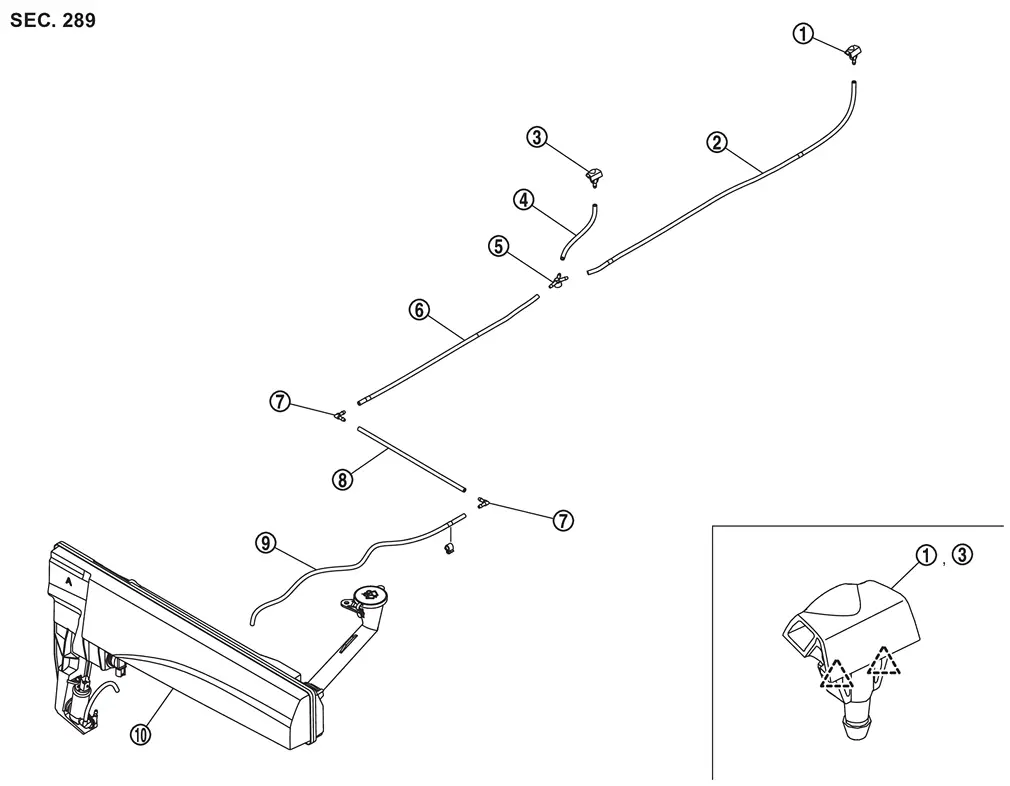
 |
Front washer nozzle LH |  |
Front washer nozzle tube LH |  |
Front washer nozzle RH |
 |
Front washer nozzle tube RH |  |
Check valve |  |
Front washer tube C |
 |
Connector |  |
Front washer tube B |  |
Front washer tube A |
 |
Washer tank assembly | ||||
 |
: Pawl | ||||
Hydraulic Layout
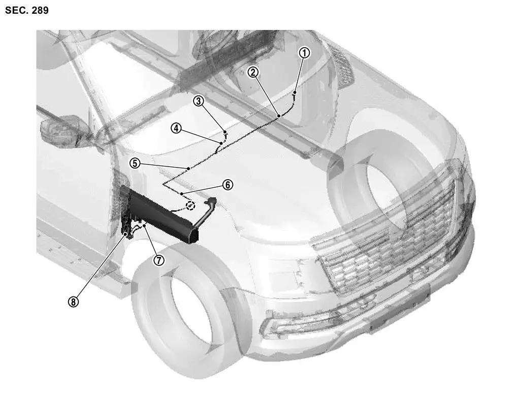
|
Front washer nozzle LH | |
Front washer nozzle tube LH | |
Front washer nozzle RH |
|
Front washer nozzle tube RH | |
Front washer tube C | |
Front washer tube B |
|
Front washer tube A | |
Washer tank assembly | ||
 |
: Clip | ||||
Front Washer Nozzle
Removal and Installation
REMOVAL
CAUTION:
When washer tube is disconnected/removed, washer fluid may come out so prepare a container to receive washer fluid and never allow washer fluid to be sprinkled.
Remove cowl top cover. Refer to Removal and Installation.
Remove front washer nozzle tube LH and RH from check valve.
While pushing front washer nozzle fixing pawls  , remove front washer nozzle with front washer nozzle tube in the direction of the arrow in the figure.
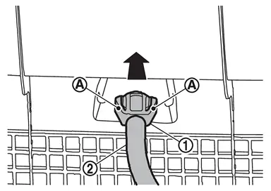
Remove front washer nozzle tube from front washer nozzle.
INSTALLATION
Note the following items, and then install in the reverse order of removal.
CAUTION:
-
Check that front washer nozzles are installed correctly, because the spray positions differ.
-
Before installation, check check valve. Refer to Inspection.
-
After installation, check front washer nozzle spray position. Refer to Inspection and Adjustment.
Inspection and Adjustment
FRONT WASHER NOZZLE SPRAY POSITION
Inspection
 NOTE:
NOTE:
Refer to the figure below for front washer nozzle spray position.
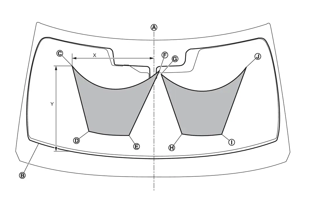
|
Center |  |
Black printed frame line | ||
 |
: Spray area |
Unit: mm (in)
 |
 |
 |
 |
 |
 |
 |
 |
|
|
X (from center) |
493.7 (19.44) |
387.7 (15.26) |
146.1 (5.75) |
43.6 (1.72) |
46.5 (1.83) |
177.0 (6.97) |
417.7 (16.44) |
570.8 (22.47) |
|
Y (from black printed frame line) |
530.2 (20.87) |
140.2 (5.52) |
138.1 (5.44) |
547.0 (21.54) |
519.6 (20.46) |
146.5 (5.77) |
122.9 (4.84) |
512.3 (20.17) |
Adjustment
CAUTION:
Front washer nozzle cannot be adjusted, so if it is out of spray position, replace front washer nozzle. Refer to Removal and Installation.
Front Washer Tube
Removal and Installation
WARNING:
REMOVAL
CAUTION:
When washer tube is disconnected/removed, washer fluid may come out so prepare a container to receive washer fluid and never allow washer fluid to be sprinkled.
Front Washer Tube A
Remove washer tank assembly. Refer to Removal and Installation.
Remove front fender drip cover RH. Refer to Removal and Installation.
Disconnect front washer tube A form connector.
Remove front washer tube A fixing clip, and then remove front washer tube A.
Front Washer Tube B
Remove front fender drip cover RH. Refer to Removal and Installation.
Disconnect front washer tube B form connectors, and then remove front washer tube B.
Front Washer Tube C
Remove cowl top cover. Refer to Removal and Installation.
Disconnect front washer tube C from check valve.
Remove washer tube C from cowl top cover.
Remove connector from front washer tube C.
INSTALLATION
Note the following items, and then install in the reverse order of removal.
CAUTION:
-
Before installation, check check valve. Refer to Inspection.
-
Align washer tube marking to the vehicle installation position.
Inspection
Check Valve
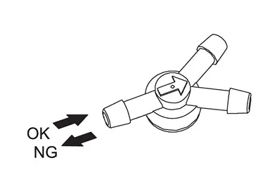
Check that air can pass through by blowing forward direction (toward nozzle side), and check that air cannot pass through by sucking reverse direction (toward washer tank side).
Other materials
Side Turn Signal Lamp
Exploded View
For exploded view of side turn signal lamp, refer to Exploded View.
Removal and Installation
CAUTION:
Disconnect the battery negative terminal or remove power circuit fuse when performing the operation for preventing electric leakage. Refer to Precautions for Removing Battery Terminal. ...
Lan System. Can Fundamental
Precautions
Precautions for Trouble Diagnosis
CAUTION:
Follow the instructions listed below. Failure to do this may cause damage to parts:
Never apply 7.0 V or more to the measurement terminal.
Use a tester with open terminal voltage of 7.0 V or less.
Turn the ignition switch OFF and disconne ...
Front Camera (driving Video Recorder)
Exploded View
Front camera (driving video recorder)
Bracket
Cover
Removal and Installation
REMOVALUsing a suitable tool, release clips , and remove cover .
Disconnect front camera (driving video recorder) harness connector.
Push to the arrow the stopper , and remove the front camera ( ...