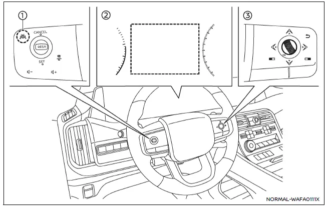
Example
- ProPILOT Assist switch
- Vehicle information display
- Steering-wheel-mounted control (right side)
Basic information
In the Nissan Armada, the Intelligent Lane Intervention (I-LI) system can be configured through the vehicle information display and steering wheel controls, providing drivers with flexible control over lane assistance features. This ensures that the Nissan Armada adapts to individual driving preferences while maintaining advanced safety functionality.
Follow these steps to enable or disable the Nissan Armada I-LI system:
1. Press the
 button repeatedly until "Settings" appears on the vehicle information display, then
confirm by pressing the scroll dial.
button repeatedly until "Settings" appears on the vehicle information display, then
confirm by pressing the scroll dial.
Use the scroll dial to navigate to "Driver Assistance" and confirm your selection.
2. Select "Lane Assist" using the scroll dial and press to confirm.
3. Choose "Intervention" and press the scroll dial again.
4. Press the ProPILOT Assist switch to activate or deactivate the Nissan Armada I-LI system.
NOTE:
- Activating ProPILOT Assist in the Nissan Armada will simultaneously enable the I-LI system and Blind Spot Intervention system. Even if I-LI is disabled in the menu, it may automatically activate when Steering Assist is engaged.
- The Nissan Armada retains your selected settings even after the engine is restarted, ensuring consistent system behavior across driving sessions.
Setting lane sensitivity
The Nissan Armada allows drivers to customize lane sensitivity levels, tailoring how early and aggressively the system responds to lane departure situations.
To adjust sensitivity:
1. Press the
 button until "Settings" appears, then confirm with the scroll dial.
Navigate to "Driver Assistance" and confirm.
2. Select "Lane Assist" and press the scroll dial.
3. Choose "Lane Sensitivity" and select one of the following options:
- Strong
- Normal
- Mild
NOTE:
The selected sensitivity level in the Nissan Armada is saved even after restarting the engine and is also applied to the Lane Departure Warning (LDW) system.
Other materials
Water Outlet and Water Piping
Exploded View
Water hose 1
Clamp
Water hose 2
Water pipe 1
Water hose 3
Electric water pump
Bracket
Clip
Water hose 4
Drain plug
O-ring
Connector
Clip
Water hose 5
Water pipe 2
Gasket
Water hose 6
Water hose 7
Water pipe assembly
...
Back Door Trim
Exploded View
Back door panel
Back door upper garnish
Back door side garnish RH
Back door lower finisher
Back door pull handle
Back door finisher cap*1
Automatic back door switch finisher*2
Back door inner finisher
Back door side garnish LH
: Clip
: Pawl
: Metal ...
Tcu
Exploded View
Steering member
Bracket
TCU
: Pawl
Removal & Installation
REMOVALCAUTION:
Before replacing TCU, perform “ADDITIONAL SERVICE WHEN REPLACING TCU". For details, refer to Work Procedure.Remove the glove box assembly. Refer to Removal and I ...