Exploded View
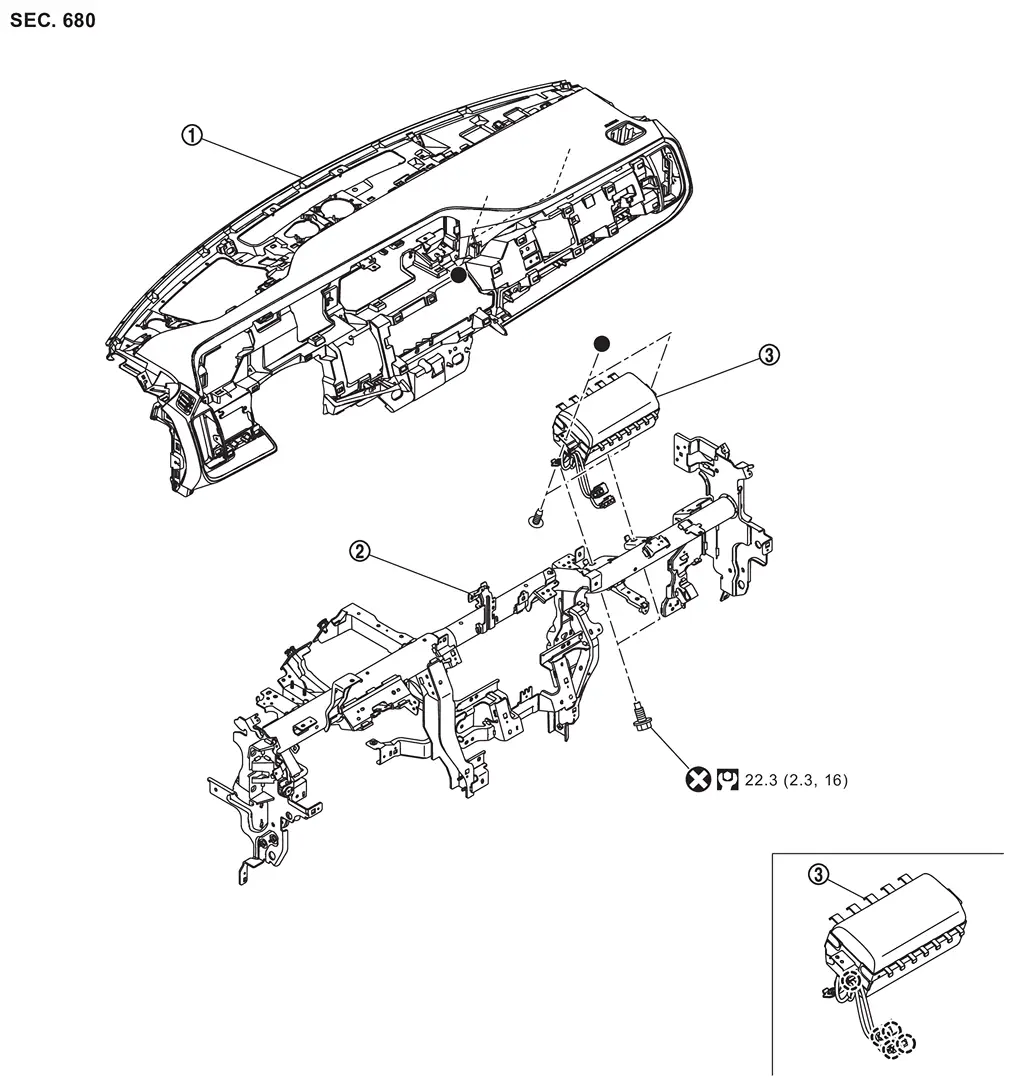
 |
Instrument panel assembly |  |
Steering member |  |
Passenger air bag module |
 |
: Clip | ||||
 |
: Always replace after every disassembly. | ||||
 |
: N·m (kg-m, ft-lb) | ||||
 : Indicates that the part is connected at points with same symbol in actual vehicle. : Indicates that the part is connected at points with same symbol in actual vehicle. |
|||||
Removal and Installation
WARNING:
Always observe the following items for preventing accidental activation.
-
Before servicing, ignition switch OFF, disconnect 12V battery negative terminal and wait for 3 minutes or more (discharges electricity held in the additional power supply circuit of the air bag diagnosis sensor unit). Refer to Precautions for Removing Battery Terminal.
-
Always work from the side of air bag module. Never work in front of it.
-
Never use air tools or electric tools for servicing.
REMOVAL
Remove instrument panel assembly from steering member. Refer to Removal and Installation.
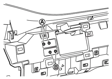
Disengage passenger air bag module harness connectors fixing clips  and
and  .
.
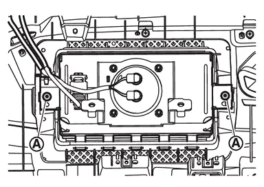
Remove passenger air bag module fixing screws .
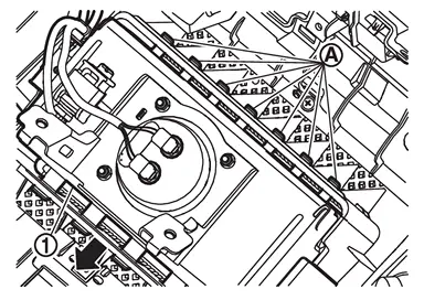
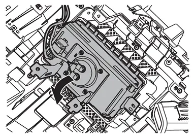
Remove passenger air bag module.Move passenger air bag according arrow direction as shown in figure, and then disengage fixing hooks .
CAUTION:
-
To prevent accidental explosion, always place the passenger air bag module with deploying direction facing upward.
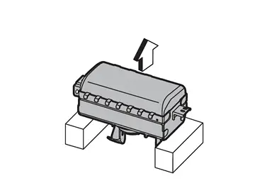
: Upward -
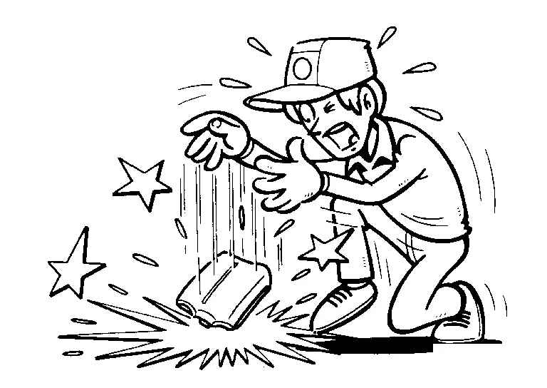
To prevent damage to the parts, never impact the passenger air bag module.
-
Replace passenger air bag module if it is dropped or sustains an impact.
-
To prevent accidental explosion, never insert any foreign objects (screwdriver, etc.) into the passenger air bag module.
-
To prevent accidental explosion, never disassemble the passenger air bag module.
-
To prevent accidental explosion, never expose the passenger air bag module to temperature of more than 90 °C (194 °F).
-
To prevent damage to the parts, never allow oil, grease, detergent, or water to come in contact with the passenger air bag module.
INSTALLATION
Note the following items, and then install in the reverse order of removal.
CAUTION:
-
Never reuse mounting bolts after removal, replace with new bolts.
-
Never damage the harness while installing.
-
After installation is completed, perform self-diagnosis using CONSULT and confirm if the system is normal. Refer to Work Flow.
-
After the work is completed, check that no system malfunction is detected by air bag warning lamp.
Other materials
Preparations
Special Service Tools
The actual shapes of TechMate tools may differ from those of special service tools illustrated here.
Tool number
(TechMate No.)
Tool name Description
(NI-39570)
Chassis ear
Locates the noise
(NI-50397)
NISSAN Squeak and Rattle Kit
Repairs the cause of noise
C ...
Door Mirror
Exploded View
Door mirror cover
Power folding motor
Door mirror finisher
Side turn signal lamp
Puddle lamp bracket (with puddle lamp)
Puddle lamp (with puddle lamp)
Door mirror housing assembly
Glass mirror
Door mirror base cover
Door mirror base gasket
Door mirror ...
Precautions
Precaution for Supplemental Restraint System (SRS) "AIR BAG" and "SEAT BELT PRE-TENSIONER"
The Supplemental Restraint System such as “AIR BAG� and “SEAT BELT PRE-TENSIONER�, used along with a front seat belt, helps to reduce the risk or severity of injury to the driver and front passenger fo ...