Exploded View
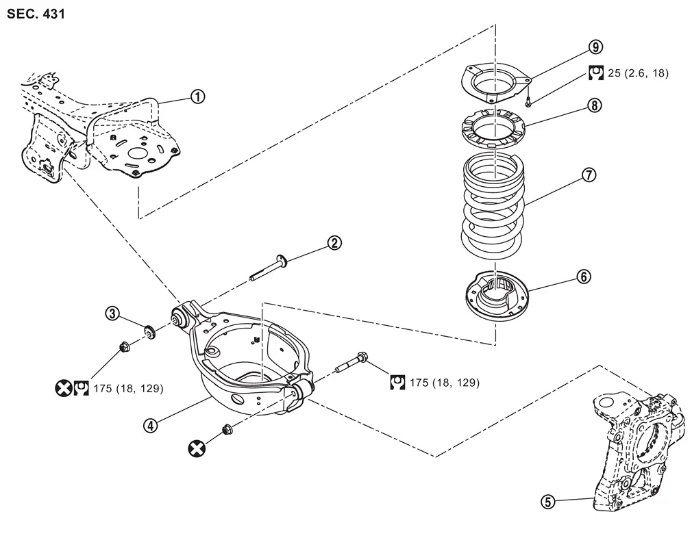
 |
Frame |  |
Adjusting bolt |  |
Eccentric disc |
 |
Rear lower link |  |
Axle housing |  |
Lower rubber seat |
 |
Coil spring |  |
Upper rubber seat |  |
Upper spring seat |
 |
: Always replace after every disassembly. | ||||
 |
: N·m (kg-m, ft-lb) | ||||
Removal and Installation
REMOVAL
Remove tires. Refer to ROAD WHEEL TIRE : Removal & Installation.
Remove wheel sensor and harness connector. Move wheel sensor in a place where it will not interfere with work. Refer to Removal and Installation.
Set suitable jack under rear lower link.
CAUTION:
-
Check the stable condition when using a suitable jack.
-
Never damage rear lower link.
Loosen rear lower link mounting nuts (frame side).
Separate rear lower link from axle housing.
Lower suitable jack, and remove coil spring.
CAUTION:
-
Check the stable condition when using a suitable jack.
-
Never damage rear lower link.
Remove lower rubber seat.
Remove upper spring seat mounting bolts, and remove upper spring seats and upper rubber seats.
Remove rear lower link mounting nut, eccentric disc, and adjusting bolt and then remove rear lower link.
Perform inspection after removal. Refer to Inspection and Adjustment.
INSTALLATION
Note the following, and install in the reverse order of removal.
-
Install coil spring
by aligning lower end of coil spring with lower rubber seat as shown in the figure.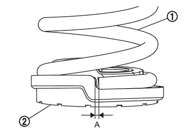
Dimension (A) : 5 mm (0.20 in) or less CAUTION:
-
Set coil spring so that its paint marks
 and are aligned with the position from the bottom end of the coil spring shown in the figure.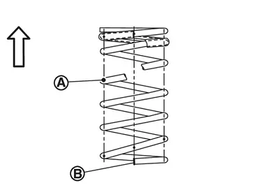
: Upper side 
: vehicle inside -
Never allow foreign matter (e.r.dust).
-
-
Perform final tighting of rear lower link by the following procedures.
-
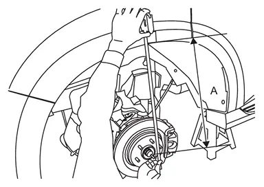
Measure between wheel center and fender arch (A).
 NOTE:
NOTE:
Note the measurements.
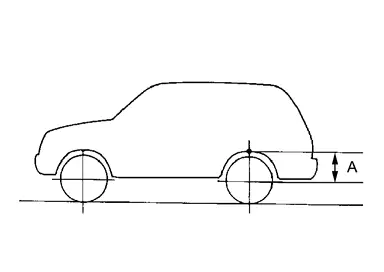
-
Set the wheel chocks on the front tires.
-
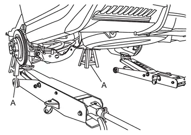
Jack up the rear of the vehicle and set the rigid rack.
-
Remove the rear tires.
-
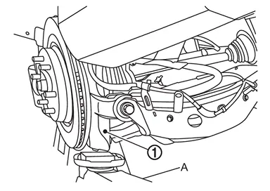
Set suitable jacks (A) on the left and right axle housings
. (axle housing ball joint fastening part).CAUTION:
Never damage threaded part of ball joint.
-
Jack up the left and right axle housings until the vehicle no longer floats off the rigid rack (A).
CAUTION:
-
Never damage axle housings.
-
Check the stable condition when using a suitable jack.
-
Never float the vehicle.
NOTE:
Jack up left and right at the same time.
-
-
Measure between wheel center and fender arch (A).
CAUTION:
-
Check the measurements are within +20 mm (0.79 in) from step 1.
-
If the measurements are +20 mm (0.79 in) or more, perform step 6 again.
-
-
Tight the mounting nuts of rear lower link to the specified torque. Refer to Exploded View.
-
-
Perform inspection after installation. Refer to Inspection.
Inspection
INSPECTION AFTER REMOVAL
Check rear lower link, bushing and coil spring for deformation, crack, and damage. Replace it if necessary.
INSPECTION AFTER INSTALLATION
Check wheel alignment. Refer to Inspection.
Other materials
Fuel-filler door
Basic information
CAUTION
Avoid directing high-pressure water, such as from a pressure washer,
onto or around the Nissan Armada fuel-filler door area.
Always ensure the fuel-filler door is securely closed before using an
automatic or high-pressure car wash.
Opening the fuel-filler do ...
Hill Start Assist system
WARNING
Never depend solely on the Hill Start Assist system in the Nissan Armada
to prevent rollback when starting on an incline. Always remain attentive and
keep full control of the vehicle. When stopped on a steep hill, firmly press
the brake pedal. Extra caution is required on icy, m ...
Memory Storing
Description
Always perform the memory storage when the driver seat control unit or steering column control module is replaced. The memory function will not operate normally if no memory storage is performed. For details, refer to Work Procedure.
Work Procedure
Memory Storage ProcedureTwo positions f ...