Exploded View
Refer to Exploded View.
Removal and Installation
CAUTION:
Always work with a helper.
REMOVAL
Remove moonroof unit assembly. Refer to Removal and Installation.
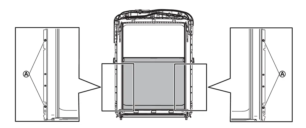
Remove rear moonroof glass fixing screws  , and then remove rear moonroof glass.
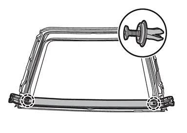
Remove fixing clips, and then remove center reinforce frame from rear moonroof glass.
 |
: Clip |
INSTALLATION
Note the following items, and then install in the reverse order of removal.
CAUTION:
-
After installing the rear moonroof glass, perform the leak test and check that there is no malfunction.
-
After installation, perform fitting adjustment. Refer to Adjustment.
Adjustment
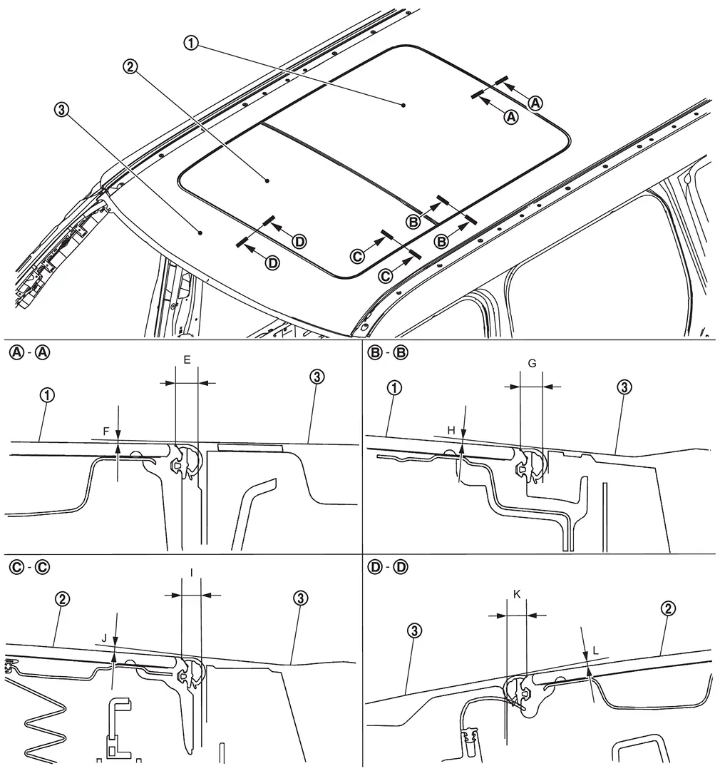
 |
Rear moonroof glass |  |
Glass lid |  |
Roof panel |
If the clearance and the surface height are out of specification, adjust them according to the procedures shown below.
 NOTE:
NOTE:
Standard of surface height is given assuming that the glass upper side status is (+), and the glass lower side status is (−) relative to the roof panel.
Unit: mm [in]
| Portion | Standard | |||
|---|---|---|---|---|
| Roof panel – Rear moonroof glass | – |
E | Clearance |
6.4 – 8.0 [0.252 – 0.315] |
| F | Surface height |
(−2.4) – (+1.0) [(−0.094) – (+0.039)] |
||
 – – |
G | Clearance |
6.1 – 8.3 [0.240 – 0.327] |
|
| H | Surface height |
(−2.4) – (+1.0) [(−0.094) – (+0.039)] |
||
| Roof panel – Glass lid |  – – |
I | Clearance |
6.4 – 8.0 [0.252 – 0.315] |
| J | Surface height |
(−2.4) – (+1.0) [(−0.094) – (+0.039)] |
||
 – – |
K | Clearance |
6.4 – 8.0 [0.252 – 0.315] |
|
| L | Surface height |
(−2.4) – (+1.0) [(−0.094) – (+0.039)] |
||
Loosen rear moonroof glass fixing screws.
Adjust the clearance of rear moonroof glass and roof panel according to the fitting standard dimension.
To prevent rear moonroof glass from moving after adjustment, first tighten the fixing screw of front left, and then tighten the fixing screw of rear right.
Tighten remaining fixing screws, being careful to prevent rear moonroof glass from moving.
CAUTION:
After adjusting the moonroof unit assembly, perform additional service. Refer to Work Procedure.
Other materials
High Pressure Fuel Pump and Fuel Hose
Exploded View
CAUTION:
Never remove or disassemble parts unless instructed as shown in the figure.
High pressure fuel pump insulator
High pressure fuel pump
O-ring
High pressure fuel pump lifter
Bracket
Holder
Fuel feed hose
To fuel rail (bank 1). ...
Fuel System
Special Service Tool
The actual shape of the TechMate tools may differ from those of the special setvice tools illustrated here.
Tool number
(TechMate No.)
Tool name Description
KV101207S0
( — )
Unified fuel lock ring wrench
Removing and installing fuel tank lock ring
KV10119800
(†...
Body Component Parts
Ultra High Strength Steel Part
DESCRIPTIONUltra high strength steel parts signify high strength steel plates with tensile strength of 980 MPa or more.When replacing parts made of ultra high strength steel or parts including ultra high strength steel, never perform the prohibition described below:PRO ...