Exploded View
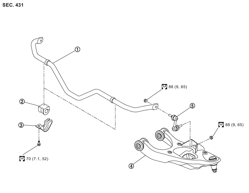
 |
Stabilizer bar |  |
Stabilizer bushing |  |
Stabilizer clamp |
 |
Front lower link  |  |
Stabilizer connecting rod | ||
 |
: N·m (kg-m, ft-lb) |
Removal and Installation
WARNING:
-
Jacking up or lift up the vehicle may the vehicle height to go down which cause a personal injury and/or damage to the air suspension component parts. Refer to Precaution for when Jacking and Lifting Up the vehicle with Electronic Air Suspension System.
REMOVAL
Remove tires. Refer to ROAD WHEEL TIRE : Removal & Installation.
Remove stabilizer connecting rod mounting nuts.
Remove mounting bolts, and remove stabilizer bar assembly from vehicle.
Remove stabilizer connecting rods, stabilizer clamps, and stabilizer bushings from stabilizer bar.
Perform inspection after removal. Refer to Inspection.
INSTALLATION
Note the following, and install in the reverse order of removal.
-
Install stabilizer bushing that slit
 becomes vehicle front side ( ).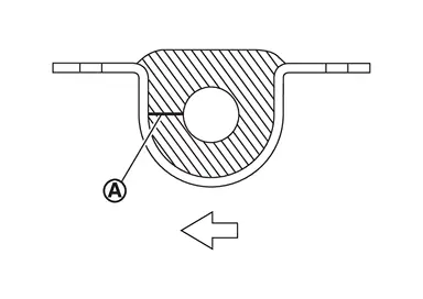
-
To installing the stabilizer connecting rod
, use a hexagonal wrench (A) to tighten the mounting nut  while preventing rotation.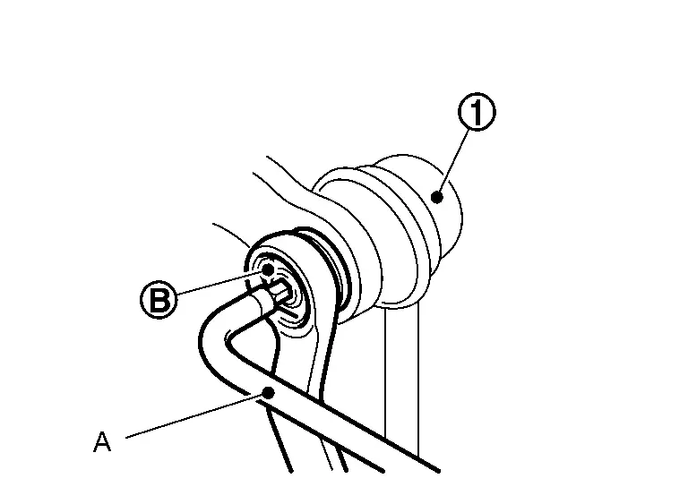
Inspection
INSPECTION AFTER REMOVAL
Check stabilizer bar, stabilizer connecting rod, stabilizer bushing and stabilizer clamp for deformation, cracks or damage. Replace it if necessary.
Other materials
Basic information
WARNING
Failure to properly follow the safety guidelines and operating instructions
for the Nissan Armada Intelligent Blind Spot Intervention (I-BSI) system may result
in serious injury or even fatal accidents.
The Nissan Armada I-BSI system is designed as a driver assistance feature
and ...
Fuel Filler Lid
Exploded View
Fuel filler base assembly
Fuel filler lid
Fuel filler lid lock assembly
Fuel filler base mask
: Pawl
: Always replace after every disassembly.
Fuel Filler Lid
Removal and Installation
REMOVAL Fully open fuel filler base assembly.
Diseng ...
Front Foot Lamp
Exploded View
Front Foot Lamp (LH)
Steering member assembly
Front foot lamp bracket (LH)
Front foot lamp (LH)
: Pawl
: vehicle front
Front Foot Lamp (RH)
Front foot lamp (RH)
Front foot lamp bracket (RH)
Passenger knee air bag module
: Pawl
: vehicle front
Front ...