
Nissan Armada 2025-2026 Service and Repair Manual: Removal and Installation
WARNING:
REMOVAL
WARNING:
CAUTION:
Release the parking brake.
Remove tires. Refer to ROAD WHEEL TIRE : Removal & Installation.
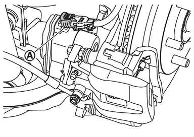
Disconnect the parking brake actuator harness connector  .
.
Remove sliding pin bolts .
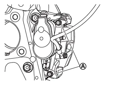
Remove the cylinder body , and suspend the cylinder body with suitable wire so that the brake hose and the electric parking brake harness will not stretch.
Remove the brake pads, shims and shim covers.
CAUTION:
Never damage the piston boots.
Never drop the brake pads, shims and shim covers.
Remember each position of the removed brake pads.
Never damage the electric parking brake harness and bracket.
Perform inspection after removal. Refer to Inspection.
INSTALLATION
WARNING:
CAUTION:
Install the brake pads to the torque member.
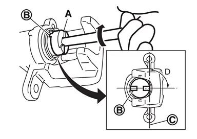
Using the brake caliper wrench (Commercial Service Tool) (A), rotate the piston clockwise so that the center line  between the dent
  of the piston and the slide pin bolt hole is 90 degree (D).
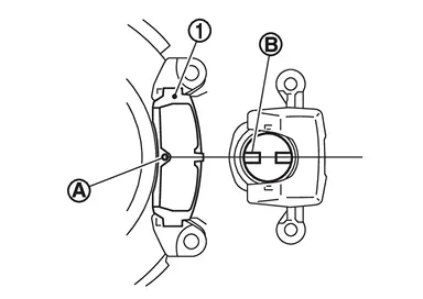
Align the protrusion of the inner pad  with the dent of the piston and attach the cylinder body to the torque member.
CAUTION:
Do not damage the piston boot.
When replacing brake pad with new one, check a brake fluid level in the reservoir tank because brake fluid returns to electrical brake control unit reservoir tank when pressing piston in.
 NOTE:
NOTE:
When returning the piston, it is easier to push the piston in using a brake caliper wrench (Commercial Service Tool).
Apply rubber grease to the sliding pins, and then install the cylinder body to torque member.
CAUTION:
Never damage the piston boot.
When replacing brake pad with new one, check a brake fluid level in the reservoir tank because brake fluid returns to reservoir tank when pressing piston in.
NOTE:Use a brake caliper wrench (commercial service tool) to easily press piston.
Install the sliding pin bolts and tighten it to the specified torque. Refer to Exploded View.
CAUTION:
Never reuse sliding pin bolt.
Connect the parking brake actuator harness connector .
Must be performed additional service when replacing brake pad. Refer to Description.
Depress the brake pedal several times to check that no drag feel is present for the rear disc brake. Refer to Inspection and Adjustment.
Install tires. Refer to ROAD WHEEL TIRE : Removal & Installation.
 Exploded View
Cylinder body Inner shim cover Inner shim Inner pad Pad wear sensor Pad retainer Torque member Outer pad Outer shim : Vehicle front : N·m (kg-m, ft-lb) : Always replace after every disa ...
 Inspection
INSPECTION AFTER REMOVAL
Replace the shims and shim covers if rust is excessively attached.
Eliminate rust on the pad and the torque member. Replace them if rust is excessively attached.
INSPECTION A ...
Other materials:
Inspection and Adjustment
FRONT WASHER NOZZLE SPRAY POSITION
Inspection
NOTE:
Refer to the figure below for front washer nozzle spray position.
Center Black printed frame line : Spray area
Unit: mm (in)
X
(from center) 493.7
(19.44) 387.7
(15.26) 146.1
(5.75) 43.6
(1.72) 46.5
(1.83) 177.0
(6.97) 417.7
(16.44) 570.8
(22. ...
Exploded View
Rear bumper side bracket LH Rear bumper bracket RH Rear bumper bracket LH Hands free sensor bracket
(with hands free sensor models) Double-sided tape
[t: 1.2 mm (0.047 in)]
(with hands free sensor models) Rear bumper fascia Rear bumper molding LH Rear bumper finisher upper Rear bumper finish ...
Exploded View
CAUTION:
Never disassemble or remove components beyond the configuration shown in the figure.
Fuel rail pressure sensor Fuel rail (bank 1) Stud bolt Fuel tube insulator Fuel tube 2 Fuel tube 1 O-ring Backup ring Injector holder Fuel injector Decoupling element Spring Seal ring Fuel ra ...

0.0048