
Nissan Armada 2025-2026 Service and Repair Manual: Removal and Installation
WARNING:
REMOVAL
WARNING:
CAUTION:
Release the parking brake.
Remove tires. Refer to ROAD WHEEL TIRE : Removal & Installation.
Remove parking brake actuator harness and rear wheel sensor. Hang parking brake actuator harness and rear wheel sensor not to interfere with work. Refer to Removal and Installation.
Fix the disc rotor using wheel nuts.
Drain brake fluid. Refer to Draining.
Remove union bolt and copper washer, and separate brake hose from brake caliper assembly. Refer to Removal and Installation.
Remove sliding pin bolts  , and remove the cylinder body.
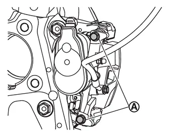
Remove torque member mounting bolts, and remove torque member.
CAUTION:
Never drop brake pad and brake caliper assembly.
Never damage the electric parking brake harness and bracket.
Remove disc rotor. Refer to Removal and Installation.
INSTALLATION
WARNING:
CAUTION:
Never allow foreign matter (e.g.dust) and oils other than brake fluid to enter the reservoir tank.
Install disc rotor. Refer to Removal and Installation.
Install the torque member to the steering knuckle and tighten the torque member mounting bolts to the specified torque. Refer to Exploded View.
CAUTION:
Never spill or splash any grease and moisture on the torque member mounting face, threads, mounting bolts and washers. Wipe out any grease and moisture.
Install the cylinder body to the torque member and tighten the sliding pin bolts to the specified torque. Refer to Exploded View.
CAUTION:
Never spill or splash any grease and moisture on the cylinder body mounting face, threads, mounting bolts and washers. Wipe out any grease and moisture.
Install brake hose and copper washers to brake caliper assembly. Refer to Removal and Installation.
CAUTION:
Never reuse copper washer.
CAUTION:
Never reuse brake fluid.
Never spill or splash brake fluid on the surface of disc rotor.
Must be performed additional service when replacing brake caliper assembly. Refer to Description.
Check a drag of rear disc brake. If any drag is found, refer to Inspection and Adjustment.
Install tires. Refer to ROAD WHEEL TIRE : Removal & Installation.
Perform inspection after installation. Refer to Inspection.
 Exploded View
REMOVAL
Brake caliper assembly : N·m (kg-m, ft-lb)
DISASSEMBLY
Cap Bleeder valve Cylinder body Sliding pin Sliding pin boot Bushing Torque member : Vehicle front : N·m (kg-m, in-lb) ...
 Disassembly and Assembly
DISASSEMBLY
NOTE:
Never remove the torque member and brake pad when disassembling and assembling the cylinder body.
Remove the sliding pin bolt, and remove the cylinder body from the torque member. Re ...
Other materials:
Exploded View
With ProPILOT ASSIST 2.1
Roof antenna : N·m (kg-m, in-lb)
Without ProPILOT ASSIST 2.1
Roof antenna : N·m (kg-m, in-lb) ...
Diagnosis Procedure
CHECK STEERING TILT MECHANISM
Check for the following.
Mechanism deformation or pinched foreign materials.
Interference with other parts because of poor installation.
Is the inspection result normal?
YES>>
GO TO 2.
NO>>
Repair or replace the malfunctioning parts.
CHECK TILT SWITCH
Che ...
Work Flow
WORK FLOW
STEP DESCRIPTION STEP 1 Get detailed information about the conditions and the environment when the incident occurred.
The following are key pieces of information required to make a good analysis: WHAT Vehicle Model, Engine, Transmission/Transaxle and the System (i.e. Radio). WHEN D ...

0.0092