
Nissan Armada 2025-2026 Service and Repair Manual: Removal and Installation
REMOVAL
CAUTION:
Never give axial impact to steering column assembly during removal.
Never move steering gear assembly when removing steering column assembly.
Never rotate the steering shaft when removing steering column assembly.
Set vehicle to the straight ahead position.
Place the tilt to the highest position. Place the telescopic to the middle position. (WITHOUT ELECTRIC MOTOR)
Place the tilt to the downest position. Place the telescopic to the longest position. (WITH ELECTRIC MOTOR)
Remove steering wheel. Refer to Removal and Installation.
Remove the cluster lid A. Refer to Removal and Installation.
Remove spiral cable. Refer to Removal and Installation.
Remove combination switch. Refer to Removal and Installation.
Remove driver knee air bag module. Refer to Removal and Installation.
Remove switch harness clips to braket (WITHOUT ELECTRIC MOTOR).
Disconnect each harness connectors installed to steering column assembly. (WITH ELECTRIC MOTOR).
Remove the upper joint fixing bolt  and nut
  (steering shaft side).
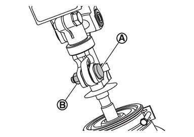
Separete the collar  and steering shaft
  from upper joint
  .
.
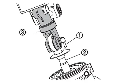
CAUTION:
When removing upper joint, never insert a tool, such as a screwdriver, into the yoke groove to pull out the upper joint. In case of the violation of the above, replace upper joint with a new one.
Remove the mounting bolts , and remove steering column assembly .
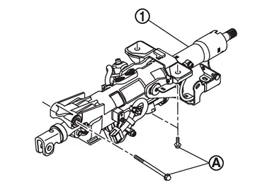
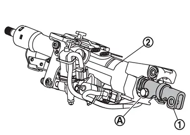
If necessary, remove upper joint and bolt from steering column assembly .
CAUTION:
Before removing the upper joint
from the steering column assembly , mark the mating part for alignment.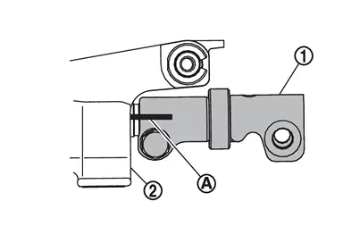
When removing upper joint, never insert a tool, such as a screwdriver, into the yoke groove to pull out the upper joint. In case of the violation of the above, replace upper joint with a new one.
Perform inspection after removal. Refer to Inspection.
INSTALLATION
Note the following, and install in the reverse order of removal.
CAUTION:
Never reuse steering shaft fixing bolt and nut.
When installing the steering column assembly, perform the following procedure.
Insert bolt
through the steering column hole.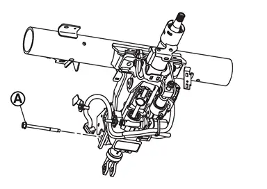
Temporary tighten the bolt with hand.
Insert bolts
through the steering column hole.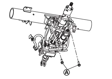
Temporary tighten the bolt with hand.
Tighten bolt
to the specified torque.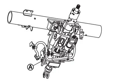
Tighten bolts
to the specified torque.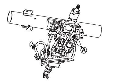
Be careful of the following points when installing the steering column assembly.
CAUTION:
Never give axial impact to steering column assembly during installation.
Never move steering gear assembly.
When replacing only the upper joint or steering column assembly with a new one, align the phase of the upper joint and steering column assembly so that the line mark stamped on the tip of the shaft of the steering column assembly faces straight up when the vehicle is traveling straight.
To install the upper joint
, align it with the matching marks on the steering column assembly put during the removal.Perform inspection after installation. Refer to Inspection.
 Exploded View
WITHOUT ELECTRIC MOTOR
Steering column assembly Upper joint : N·m (kg-m, ft-lb)
WITH ELECTRIC MOTOR
Steering column assembly Upper joint : N·m (kg-m, ft-lb) ...
 Inspection
INSPECTION AFTER REMOVAL
Check the following items and replace, if necessary.
Check each part of steering column assembly for damage or other malfunctions. Replace if there are any abnormal conditions ...
Other materials:
Disposal
CAUTION:
When performing disposal operation, wear the protective glasses and protective gloves.
Fix back door stay using a vise (C).
CAUTION:
When cutting a hole on back door stay, always cover a hacksaw (A) using a shop cloth (B) to avoid scattering metal fragments or oil.
Using hacksaw slowly m ...
SERVICE NOTICE AND PRECAUTIONS FOR TPMS : Precautions
Low tire pressure warning lamp turns ON when tire pressure is less than warning tire pressure value. Adjust tire pressure for all wheels to the specified value. Refer to TIRE AIR PRESSURE : Service Data.
Low tire pressure warning lamp blinks for 1 minute, then turns ON when occurring any malfunctio ...
Commercial Service Tools
Tool name Description Oil seal remover
Removing side oil seal
Removing front oil seal
Sliding hammer
Removing differential assembly Flange wrench
Removing and installing drive pinion lock nut Puller
Removing companion flange Separator
Removing pinion rear bearing inner race Power t ...

0.0067