Exploded View
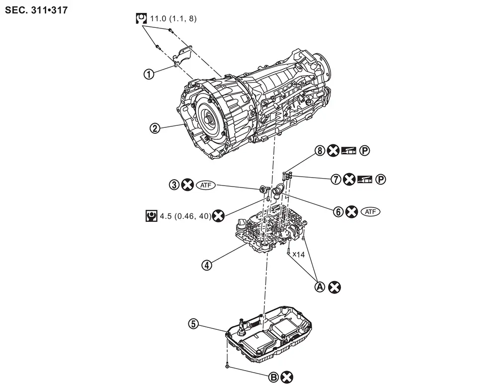
 |
Heat shield |  |
A/T assembly |  |
Joint tube |
 |
Control valve & TCM |  |
Oil pan |  |
Joint tube |
 |
Joint tube |  |
Tube | ||
 |
Refer to Removal and Installation. |  |
Refer to Removal and Installation. | ||
 |
: N·m (kg-m, ft-lb) | ||||
 |
: N·m (kg-m, in-lb) | ||||
 |
: Always replace after every disassembly. | ||||
 |
: Apply ATF | ||||
 |
: Apply petroleum jelly. | ||||
Removal and Installation
WARNING:
-
Jacking up or lift up the vehicle may the vehicle height to go down which cause a personal injury and/or damage to the air suspension component parts. Refer to Precaution for when Jacking and Lifting Up the vehicle with Electronic Air Suspension System.
REMOVAL
Remove oil pan. Refer to Removal and Installation.
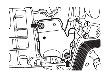
Remove heat shield mounting bolts ( ) and heat shield .
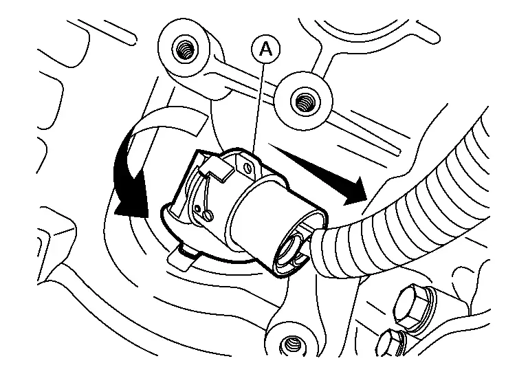
Disconnect harness connector from control valve & TCM.
 NOTE:
NOTE:
Rotate connector counterclockwise then pull out to remove as shown.
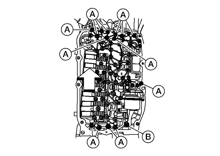
Remove control valve & TCM mounting bolts and from the control valve & TCM.
CAUTION:
Never reuse bolts.
| : vehicle front |
| Bolt symbol | Length mm (in) | Number of bolts |
|---|---|---|
| A | 32 (1.26) | 14 |
| B | 18 (0.71) | 1 |
Insert RQ transmission guide pins (SST: NI–52983) (B) to A/T assembly using holes .
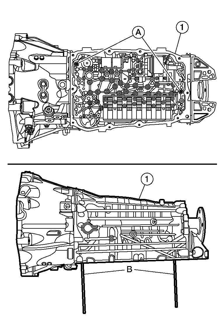
CAUTION:
Never reuse bolts.
Remove the control valve & TCM from the A/T assembly using RQ transmission guide pins (SST: NI–52983) (A).
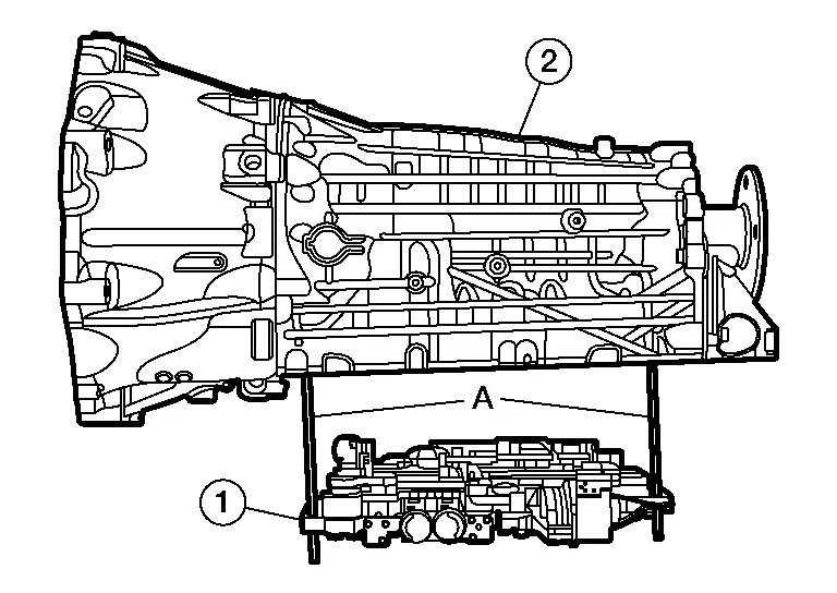
NOTE:
The weight of the valve body (control valve & TCM) is approximately 10 kg (22 lbs.).
Remove joint tubes and .
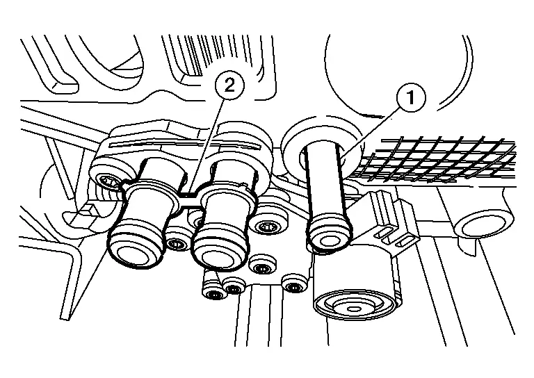
CAUTION:
Never reuse joint tubes.
NOTE:
Joint tubes may come out when removing control valve & TCM.
INSTALLATION
Note the following, and install in the reverse order of removal.
CAUTION:
-
Be careful not to damage connector when installing any connector.
-
Never reuse joint tubes.
-
Apply A/T fluid to O-ring of joint tubes.
-
Never reuse control valve & TCM bolts.
-
Never reuse drain plug O-ring. In addition, install new drain plug O-ring after adjustment of A/T fluid filling.
Refer to the following when installing the control valve & TCM to transmission case.
Install joint tubes and .
CAUTION:
-
Never reuse joint tubes.
-
Apply petroleum jelly to joint tubes
and to hold in place during installation.
NOTE:
Install joint tube with narrow opening facing toward control valve & TCM into A/T assembly .
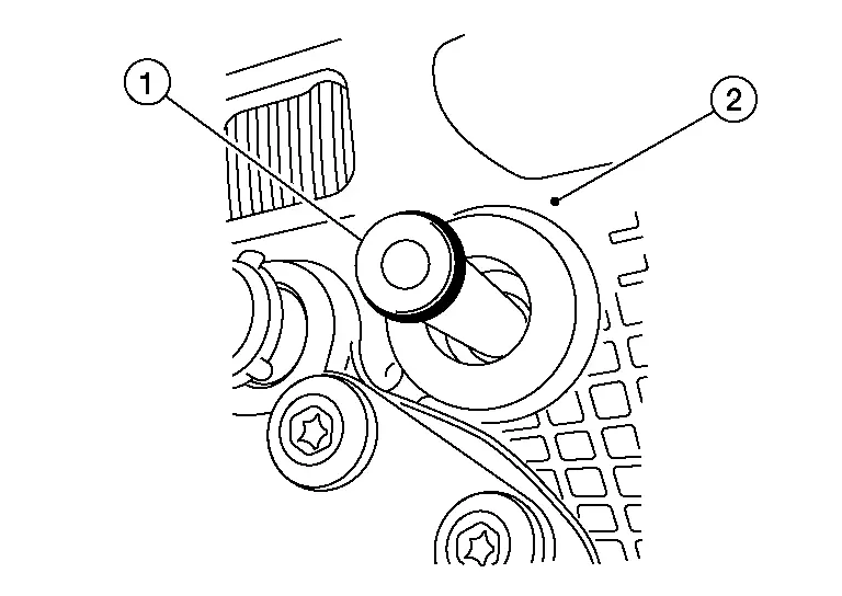
Install RQ transmission guide pins (SST: NI–52983) (A) to the A/T assembly as shown.
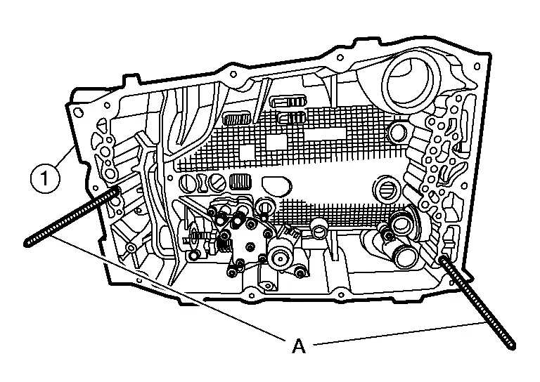
Install the control valve TCM to the A/T assembly using RQ transmission guide pins (SST: NI–52983) (A).
NOTE:
Control valve TCM will click into place when fully seated in A/T assembly.
Hand tighten control valve & TCM bolts before removing guide pins (commercial service tool).
CAUTION:
Never reuse control valve & TCM bolts.
| : vehicle front |
| Bolt symbol | Length mm (in) | Number of bolts |
|---|---|---|
| A | 32 (1.26) | 14 |
| B | 18 (0.71) | 1 |
Replace RQ transmission guide pins (SST: NI–52983) (A) with control valve & TCM bolts.
Install the control valve & TCM bolts and , then tighten to the specification shown.
| Step 1 | : Tighten 4.0 N·m (0.41 kg-m, 35 in-lb) |
| Step 2 | : Tighten 95° |
Inspection and Adjustment
INSPECTION AFTER REMOVAL
Check foreign materials in oil pan to help determine causes of malfunction. If the A/T fluid is very dark, smells burned, or contains foreign particles, the frictional material (clutches) may need replacement. A tacky film that will not wipe clean indicates varnish build up. Varnish can cause valves and clutches to stick and can inhibit pump pressure.
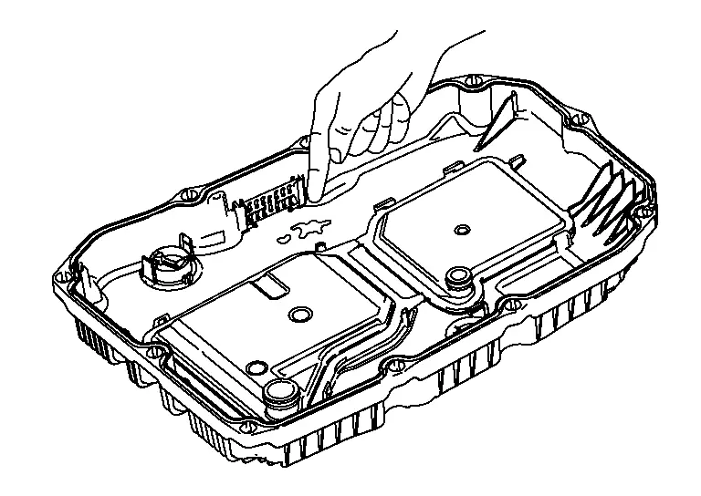
-
If frictional material is detected, perform A/T fluid cooler cleaning. Refer to Cleaning.
INSPECTION AFTER INSTALLATION
Start the engine and check visually that there is no leakage of A/T fluid.
ADJUSTMENT AFTER INSTALLATION
When replaced the control valve & TCM, perform “ADDITIONAL SERVICE WHEN REPLACING CONTROL VALVE & TCM�. Refer to Description.
Other materials
Difference between predictive and actual distances
Basic information
The Nissan Armada RearView Monitor provides reference guidelines only. The actual
distance to objects may differ depending on terrain and object positioning.
On uneven surfaces such as slopes or when objects extend outward, the displayed
distance may not accurately reflect re ...
Diagnosis and Repair Work Flow
Work Flow
DETAILED FLOWINTERVIEW FROM THE CUSTOMER
CAUTION:
Customers are not professional. Never guess easily like “maybe the customer means that...,� or “maybe the customer mentions this symptom�.
>>
GO TO 2.
CHECK SYMPTOM
Reproduce the symptom that is indicated by the customer, b ...
City Models
Exploded View
Front bumper side bracket RH
Front bumper side retainer RH
Front bumper retainer
Front bumper side stay RH
Front bumper reinforcement
Seal
Front bumper energy absorber A
Front bumper energy absorber B
Front bumper fascia
Front bumper side finisher RH
Lic ...