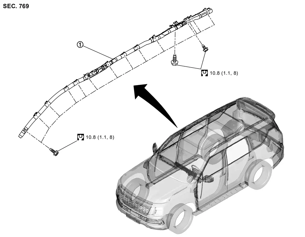
Exploded View
 |
Curtain airbag module | ||||
 |
: N·m (kg-m, ft-lb) | ||||
Removal and Installation
WARNING:
Always observe the following items for preventing accidental activation.
-
Before servicing, ignition switch OFF, disconnect 12V battery negative terminal and wait for 3 minutes or more (discharges electricity held in the additional power supply circuit of the air bag diagnosis sensor unit). Refer to Precautions for Removing Battery Terminal.
-
Always work from the side of air bag module. Never work in front of it.
-
Never use air tools or electric tools for servicing.
REMOVAL
Remove headlining assembly. Refer to Removal and Installation.
Disconnect curtain air bag module harness connectors  and
and  .
.
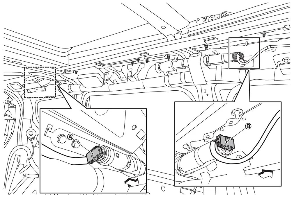
| : vehicle front |
CAUTION:
-
Never damage harness connector.
-
Insert remover tool (A) wrapped in tape between connector and lever
, and then disconnect harness connector while moving the lever.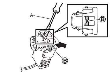
Remove curtain air bag module mounting bolts.
Remove bracket part of curtain air bag module from vehicle, and then remove curtain air bag module.
CAUTION:
-
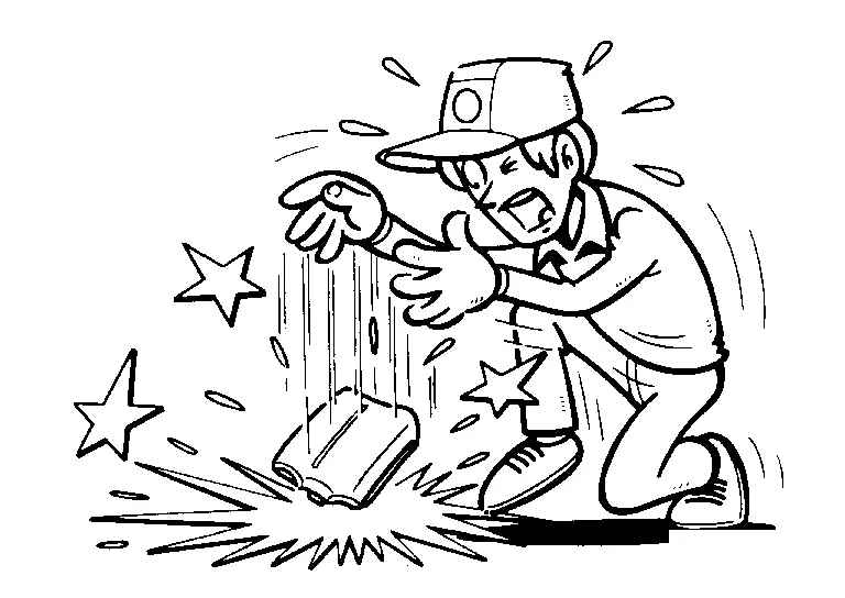
To prevent damage to the parts, never impact the curtain air bag module.
-
Replace curtain air bag module if it is dropped or sustains an impact.
-
To prevent accidental explosion, never insert any foreign objects (screwdriver, etc.) into the curtain air bag module.
-
To prevent accidental explosion, never disassemble the curtain air bag module.
-
To prevent accidental explosion, never expose the curtain air bag module to temperatures of more than 90°C (194°F).
-
To prevent damage to the parts, never allow oil, grease, detergent, or water to come in contact with the curtain air bag module.
INSTALLATION
Note the following items, and then install in the reverse order of removal.
CAUTION:
-
When installing, tighten mounting bolts according to numerical order as shown in figure.
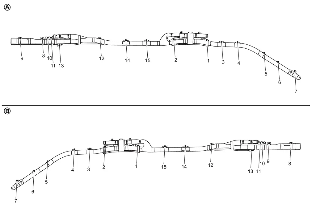
: Left side : Right side -
Never damage the harness while installing.
-
When connect curtain air bag harness connector, press harness connector until clicking sound.
-
After installing the connector, check that the lock is pushed securely into it.
-
After installation is completed, perform self-diagnosis using CONSULT and confirm if the system is normal. Refer to Work Flow.
-
After the work is completed, check that no system malfunction is detected by air bag warning lamp.
Other materials
Steering System Service Data and Specifications
Steering Wheel
Item Standard
Steering wheel axial end play
0 mm (0 in)
Steering wheel play on the outer circumference
0 – 35 mm (0 – 1.38 in)
Steering wheel turning force
34 N (3.5 kgf, 7.6 lbf) or less
Steering Angle
WITHOUT DINAMIC DIGITAL SUSPENSION AND ELECTRONIC AIR SUSPE ...
Front
Exploded View
Side defroster nozzle RH
Center defroster nozzle
Side defroster nozzle LH
Instrument panel assembly
Side ventilator grille LH
Instrument finisher A
Ionizer
(with ionizer models)
Side ventilator duct 1 LH
Side ventilator duct 3 LH
Side ventilator duct 2 L ...
Diagnosis and Repair Work Flow
Work Flow
OVERALL SEQUENCEDETAILED FLOWINTERVIEW FOR MALFUNCTION
Interview the symptom to the customer.
>>
GO TO 2.
SYMPTOM CHECK
Check the symptom from the customer's information.
>>
GO TO 3.
FAIL-SAFE ACTIVATION CHECK
Check that the symptom is applied to the fail-safe activation.
D ...