Exploded View
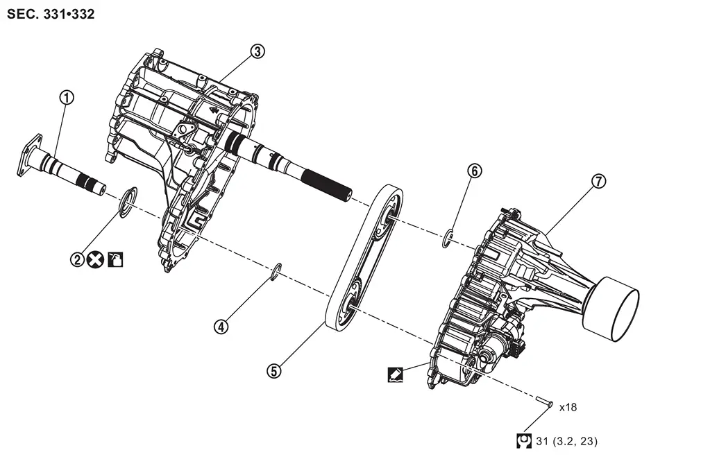
 |
Front output shaft |  |
Front oil seal |  |
Front case |
 |
Snap ring |  |
Sprockets with chain |  |
Snap ring |
 |
Rear case | ||||
 |
: Always replace after every disassembly. | ||||
 |
: N·m (kg-m, ft-lb) | ||||
 |
: Apply transfer fluid. | ||||
 |
: Apply Genuine Liquid Gasket, Loctite 598 or equivalent. | ||||
Removal and Installation
WARNING:
-
Jacking up or lift up the vehicle may the vehicle height to go down which cause a personal injury and/or damage to the air suspension component parts. Refer to Precaution for when Jacking and Lifting Up the vehicle with Electronic Air Suspension System.
REMOVAL
Drain transfer fluid. Refer to Draining.
Remove transfer assembly from vehicle. Refer to Removal and Installation.
Remove the rear case mounting bolts  .
.
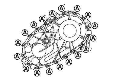
| * | : Tighten together with the bracket. |
Remove the rear case .
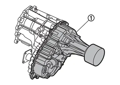
Remove the rear output shaft snap ring .
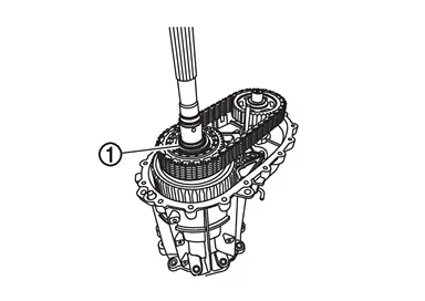
Remove the sprockets with chain from front case .
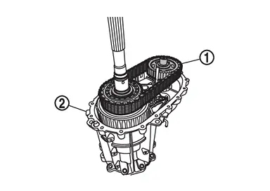
Remove the front output shaft snap ring .
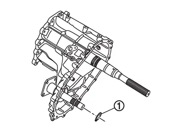
Remove the front output shaft from front case .
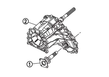
CAUTION:
Never damage the output shaft.
Remove the front oil seal form front case .
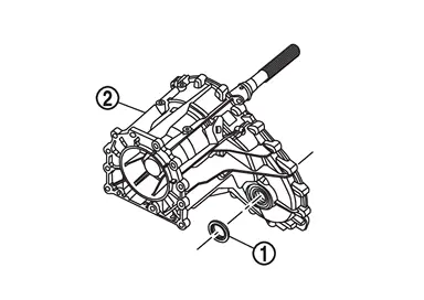
CAUTION:
Never damage the front case.
INSTALLATION
Install front oil seal with a drift (A) (commercial service tool) within the dimension (L) shown as follows.
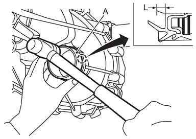
| L | : 1.7 – 2.3 mm (0.067 – 0.091 in) |
CAUTION:
-
Never reuse front oil seal.
-
Apply transfer fluid onto circumference of oil seal.
-
When installing, never incline front oil seal.
-
Never handle the oil seal inner periphery and oil seal lip.
Install the front output shaft to front case .
CAUTION:
Never damage the front oil seal lip.
Install the front output shaft snap ring .
Install the sprockets with chain to front case .
Install the rear output shaft snap ring .
Apply sealant to mating surface of rear case.
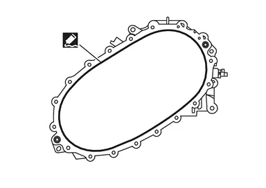
-
For applying sealant, refer to Exploded View.
Install the rear case .
Tightening the rear case mounting bolts to the specified torque. Refer to Exploded View.
| * | : Tightening the bolt with bracket. |
Install transfer assembly. Refer to Removal and Installation.
Fill with new transfer fluid. Refer to Refilling.
Inspection
INSPECTION AFTER INSTALLATION
Check fluid leakage and the fluid level. Refer to Inspection.
ADJUSTMENT AFTER INSTALLATION
When transfer case component parts are removed, performe writing unit parameter. Refer to Description.
Other materials
Basic Inspection
Work Procedure
INSPECTION START
Check service records for any recent repairs that may indicate a related malfunction, or a current need for scheduled maintenance.
Open engine hood and check the following:
Harness connectors for improper connections
Wiring harness for improper connections, p ...
Noise, Vibration, and Harshness (nvh) Troubleshooting
NVH Troubleshooting Chart
Use the chart below to find the cause of the symptom. If necessary, repair or replace these parts. Possible cause and SUSPECTED PARTS Symptom Reference
Vibration Shake Noise
Uneven rotating torque
×
×
Inspection
Center bearing improper installation
× ...
Battery Inspection
How to Handle Battery
CAUTION:
After connecting battery cables, ensure that they are tightly clamped to battery terminals for good contact.WHERE TO CONNECT JUMPER CABLE WHEN THE 12V BATTERY IS DISCHARGEDCAUTION:
If it becomes necessary to start the engine with a booster battery and jumper cables, ...