Exploded View
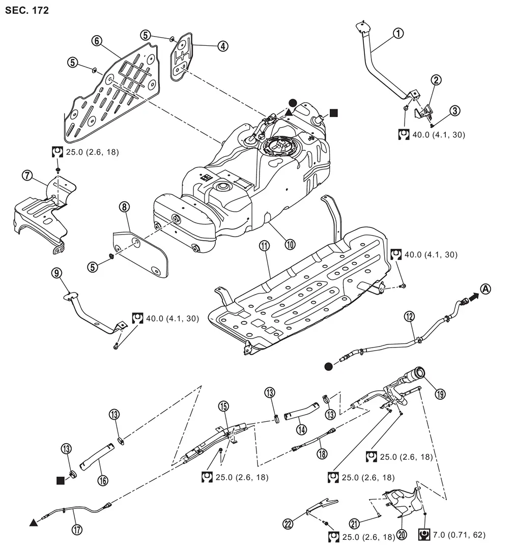
 |
Fuel tank mounting band (Rear) |  |
Fuel tank mounting band cover |  |
Clip 1 |
 |
Fuel tank side protector 1 |  |
Clip 2 |  |
Fuel tank side protector 2 |
 |
Fuel tank upper protector |  |
Fuel tank front protector |  |
Fuel tank mounting band (Front) |
 |
Fuel tank |  |
Fuel tank protector |  |
Vent tube |
 |
Clamp |  |
Fuel filler hose 1 |  |
Fuel filler tube 2 |
 |
Fuel filler hose 2 |  |
EVAP tube 2 |  |
EVAP tube 1 |
 |
Fuel filler tube 1 |  |
Fuel filler tube protector 1 |  |
Clip 3 |
 |
Fuel filler tube protector 2 | ||||
 |
To EVAP canister. Refer to EVAP CANISTER : Exploded View. | ||||
 |
: N·m (kg-m, ft-lb) | ||||
 |
: N·m (kg-m, in-lb) | ||||
 , , , ,   : Indicates that the part is connected at points with same symbol in actual vehicle.  : Indicates that the part is connected at points with same symbol in actual vehicle. |
|||||
Removal & Installation
WARNING:
Jacking up or lift up the vehicle may the vehicle height to go down which cause a personal injury and/or damage to the air suspension component parts. Refer to Precaution for when Jacking and Lifting Up the vehicle with Electronic Air Suspension System.
REMOVAL
WARNING:
Be sure to read “General Precautions� when working on the fuel system. Refer to GENERAL PRECAUTION : Precautions.
Perform steps 1 to 7 of “REMOVAL� in “ FUEL LEVEL SENSOR UNIT, FUEL FILTER AND FUEL PUMP ASSEMBLY� on main fuel level sensor unit. Refer to FUEL LEVEL SENSOR UNIT, FUEL FILTER AND FUEL PUMP ASSEMBLY : Removal & Installation.
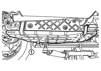
Remove fuel tank protector .
Remove fuel tank side protector 1 .
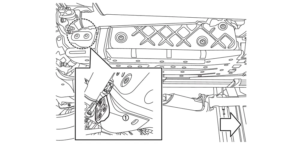
| : vehicle front |
Support center of fuel tank with transmission jack (A).
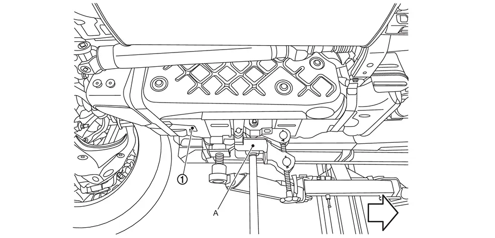
| : vehicle front |
Remove fuel tank bands .
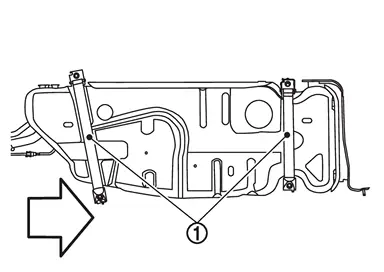
| : vehicle front |
Lower fuel tank 100 mm (3.94 in).
Disconnect fuel filler hose 2 , vent tube and EVAP tube 2 at fuel tank side.
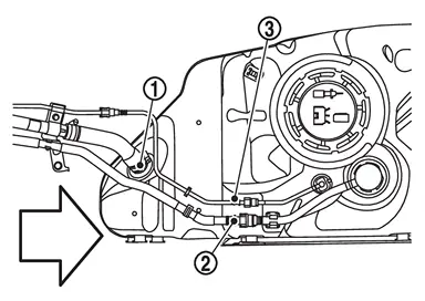
| : vehicle front |
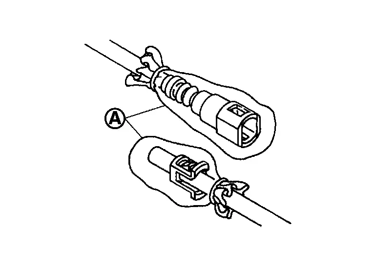
Hold the sides of quick connector, push in tabs and pull out vent tube and EVAP tube 2.
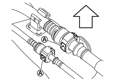
| : vehicle upper |
CAUTION:
Quick connector can be disconnected when the tabs are completely depressed. Never twist it more than necessary.
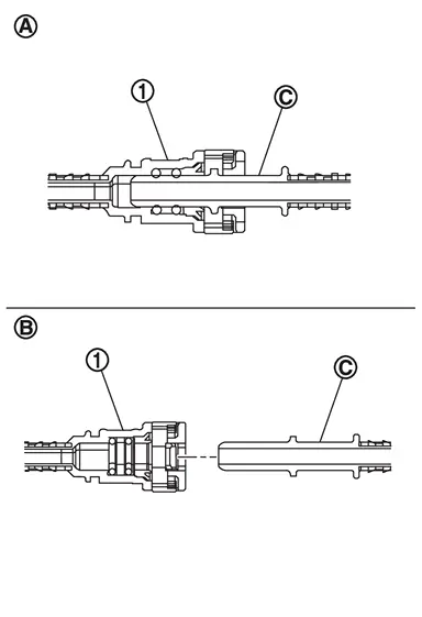
|
: Connection (Crosssection) |
 |
: Disconnection |
 |
: Hard tube |
-
Never use any tools to disconnected quick connector.
-
Prevent acid liquid such as battery electrolyte, etc. from getting on resin tube.
-
Never bend or twist resin tube during installation and disconnection.
-
Never insert plug, preventing damage to O-ring in quick connector.
-
To keep the connecting portion clean and to avoid damage and foreign materials, cover them completely with plastic bags
or something similar.
Supporting with hands, descend transmission jack carefully, and remove fuel tank.
CAUTION:
-
Fuel tank may be in an unstable condition, due to the shape of the fuel tank bottom. Be sure to secure tank at all times.
-
Check that all connection points have been disconnected.
-
Confirm there is no interference with vehicle.
If replacing the fuel tank, remove the fuel level sensor unit, fuel filter and fuel pump assembly to transfer to the new fuel tank. Remove and discard the O-ring. Refer to FUEL LEVEL SENSOR UNIT, FUEL FILTER AND FUEL PUMP ASSEMBLY : Removal & Installation.
Inspection
INSPECTION AFTER INSTALLATION
Use the following procedure to check for fuel leakage.
Ignition switch “ON� (with engine stopped), and check connections for leakage by applying fuel pressure to fuel piping.
Start engine and rev it up and check there are no fuel leakage at the fuel system tube and hose connections.
Other materials
Basic information
CAUTION
Always use the Nissan Armada power outlets with the engine running to
prevent battery discharge.
Avoid using the power outlets simultaneously with high electrical loads
such as air conditioning, headlights, or defrosters.
Ensure all connected devices are turned OFF before plugg ...
Differential Assembly
Exploded View
Bracket
Side oil seal
Rear final drive assembly
Differential lock position switch
Rear cover
Gasket
Drain plug
Stud bolt
Filler plug
O-ring
: N·m (kg-m, in-lb)
: N·m (kg-m, ft-lb)
: Always replace after every disassemb ...
Precautions
Precaution for Supplemental Restraint System (SRS) "AIR BAG" and "SEAT BELT PRE-TENSIONER"
The Supplemental Restraint System such as “AIR BAG� and “SEAT BELT PRE-TENSIONER�, used along with a front seat belt, helps to reduce the risk or severity of injury to the driver and front passenger fo ...