Exploded View
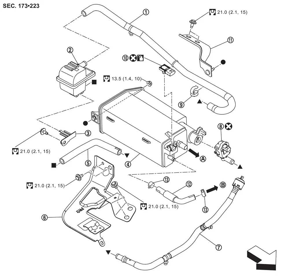
 |
Vent hose 1 |  |
Canister filter |  |
Bracket 3 |
 |
EVAP canister |  |
Vent hose 2 |  |
Bracket 1 |
 |
Vent hose 3 |  |
EVAP canister vent control valve |  |
Clip |
 |
EVAP control system pressure sensor |  |
Bracket 2 |  |
Vent hose 4 |
 |
Clamp | ||||
 |
To fuel tank. Refer to FUEL TANK : Exploded View. |  |
To engine. Refer to Hydraulic Layout. | ||
| : vehicle front | |||||
 |
: Always replace after every disassembly. | ||||
 |
: N·m (kg-m, ft-lb) | ||||
 |
: Should be lubricated with oil. | ||||
 , , , ,  , ,  : Indicates that the parts is connected at points with same symbols in actual vehicle. : Indicates that the parts is connected at points with same symbols in actual vehicle. |
|||||
Hydraulic Layout
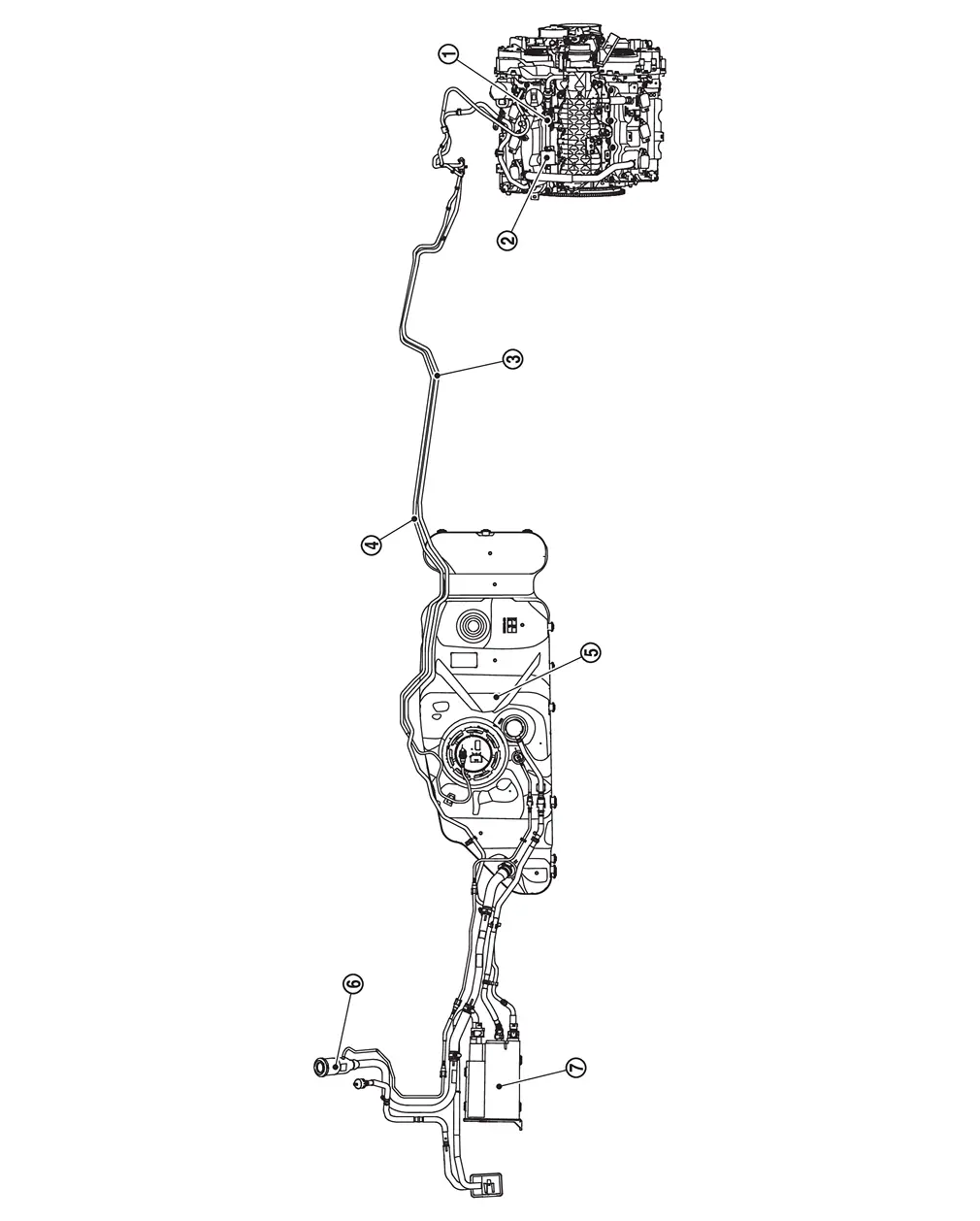
|
EVAP canister purge volume control solenoid valve | |
EVAP resonator | |
EVAP line |
|
Fuel line | |
Fuel tank | |
Fuel filler neck |
|
EVAP canister |
Removal & Installation
WARNING:
Jacking up or lift up the vehicle may the vehicle height to go down which cause a personal injury and/or damage to the air suspension component parts. Refer to Precaution for when Jacking and Lifting Up the vehicle with Electronic Air Suspension System.
REMOVAL
EVAP canister
Remove spare tire. Refer to Removal & Installation.
Disconnect EVAP control system pressure sensor harness connector and vent hose 4 from EVAP canister .
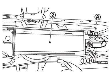
Disconnect EVAP canister vent control valve harness connector and vent hose 1 from EVAP canister .
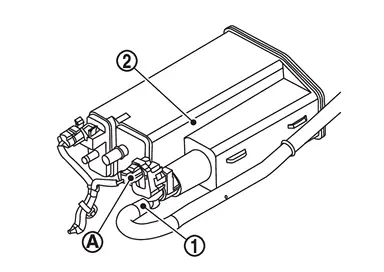
Hold the sides of connector, push in tabs and pull out vent tube.
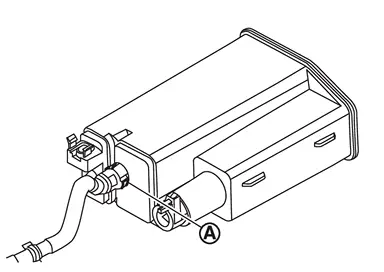
Remove mounting bolt and mounting nut of bracket 1, and remove bracket 1 and EVAP canister as a set from the vehicle
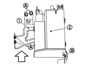
| : vehicle front |
 NOTE:
NOTE:
The EVAP canister vent control valve and EVAP control system pressure sensor can be removed without removing the EVAP canister.
Remove EVAP canister from bracket 1.
Canister filter
Remove vent hose 1 and vent hose 2 from canister filter .
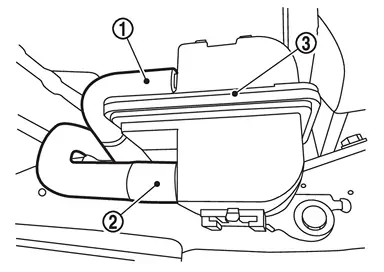
Remove canister filter from b racket 3.
Remove vent hose 1 and vent hose 2 from the vehicle if necessary.
INSTALLATION
Install in the reverse order of removal.
NOTE:
Tighten EVAP canister mounting bolt to the specified torque.
Disassembly and Assembly
DISASSEMBLY
Disengage the pawl and turn EVAP canister vent control valve counterclockwise.
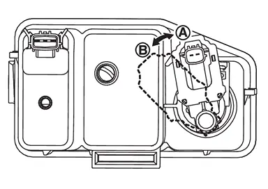
|
: Lock |
|
: Unlock |
Remove the EVAP canister vent control valve.
ASSEMBLY
Assemble in the reverse order of disassembly.
CAUTION:
Do not reuse O-rings.
Inspection
Check EVAP canister as per the following:
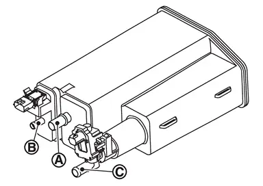
Block port .
Blow air into port and check that it flows freely out of port  .
.
Release blocked port .
Apply vacuum pressure to port and check that vacuum pressure exists at the ports and .
Block port and .
Apply pressure to port and check that there is no leakage.
Other materials
Traffic Sign Recognition (TSR)
Basic information
The Nissan Armada Traffic Sign Recognition (TSR) system is designed to enhance
driver awareness by identifying and displaying the most recently detected road signs,
particularly speed limits. Using the advanced multi-sensing front camera unit positioned
near the interior ...
Rear Center Console Assembly
Exploded View
REMOVAL
Rear center tray cup holder mat
Rear center tray front mask
Rear center tray assembly
Rear center tray rear mask
Rear center pocket mat
: Pawl
DISASSEMBLY
Rear center tray assembly
Rear center tray reinforcement
Removal and ...
Transfer Fluid: Atx93b
Inspection
WARNING:
Jacking up or lift up the vehicle may the vehicle height to go down which cause a personal injury and/or damage to the air suspension component parts. Refer to Precaution for when Jacking and Lifting Up the vehicle with Electronic Air Suspension System.
FLUID LEAKAGECheck t ...