Exploded View
REMOVAL
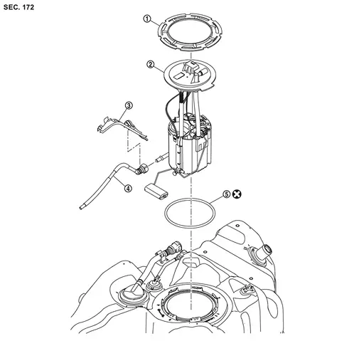
 |
Lock ring |  |
Fuel level sensor unit, fuel filter and fuel pump assembly |  |
Transfer tube bracket |
 |
Transfer tube |  |
O-ring | ||
 |
: Always replace after every disassembly. | ||||
DISASSEMBLY
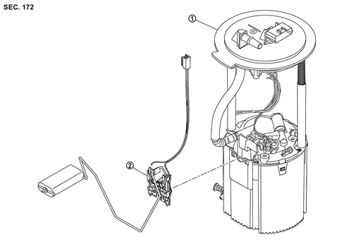
|
Fuel filter and fuel pump assembly | |
Fuel level sensor unit |
Removal & Installation
WARNING:
Jacking up or lift up the vehicle may the vehicle height to go down which cause a personal injury and/or damage to the air suspension component parts. Refer to Precaution for when Jacking and Lifting Up the vehicle with Electronic Air Suspension System.
WARNING:
Be sure to read “General Precautions� when working on the fuel system. Refer to GENERAL PRECAUTION : Precautions.
REMOVAL
Check fuel level on a level ground. If the fuel level is 7/8 of the fuel tank (full or nearly full), draw appropriate amount of fuel from the fuel tank.
| Guideline | : Draw approximately 20 liters (5-2/8 us gal, 4-3/8 Imp gal) from a full-tank condition. |
-
In the event of fuel pump malfunction, first insert the filler tube guide [service setting part: 17261 6RA0A] into the filler port,then insert a 16 mm (0.63 in) diameter hose into the filler tube guide andpump approximately 20 liters (5-2/8 us gal, 4-3/8 Imp gal) fuel.
Release the fuel pressure from the fuel lines. Refer to Work Procedure.
Open fuel filler lid.
Insert a general purpose pipe with the dimensions shown in fuel filler cap less unit and release the pressure inside the fuel tank.
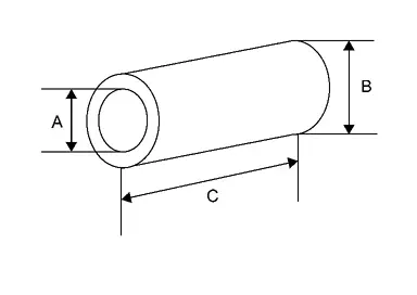
| A | : Over Φ 16 mm (0.63 in) |
| B | : Φ 21.0 mm (0.83 in) |
| C | : 150 mm (5.91 in) |
 NOTE:
NOTE:
Insert and hold 80 mm (3.15 in) from the end of the general purpose pipe into the fuel filler port.
Remove LH side of the second seat.Refer to following :
-
CAPTAIN SEAT : Refer to Removal and Installation.
-
BENCH SEAT : Refer to Removal and Installation.
Peel off floor carpet, then remove inspection hole cover by turning clips clockwise by 90 degrees  .
.
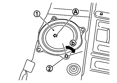
 |
: vehicle front mark |
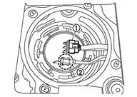
Disconnect harness connector and fuel feed tube .
Disconnect quick connector as follows:
-
Hold the sides of connector, push in tabs and pull out fuel feed tube.
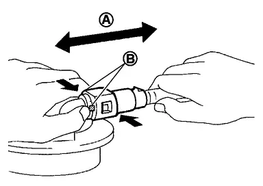
: Pull 
: Push in tabs -
If quick connector sticks to tube of main fuel level sensor unit, push and pull quick connector several times until they start to move. Then disconnect them by pulling.
CAUTION:
-
Quick connector
can be disconnected when the tabs  are completely depressed. Never twist it more than necessary.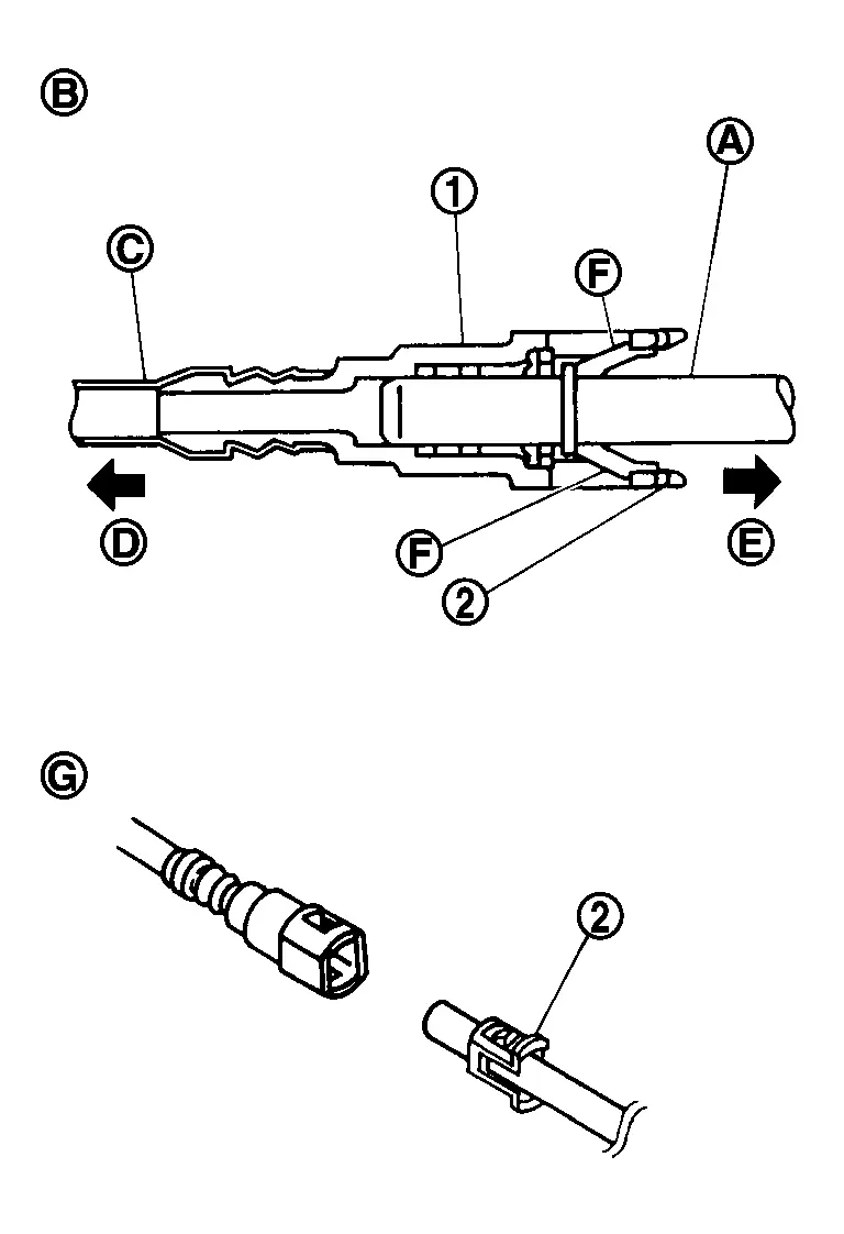
: Connection (Cross-section) 
: To under floor fuel line 
: To fuel tank 
: Disconnection -
Never use any tools to disconnected quick connector.
-
Keep resin tube
 away from heat. Be especially careful when welding near the resin tube.
 -
Prevent acid liquid such as battery electrolyte, etc. from getting on resin tube.
-
Never bend or twist resin tube during installation and disconnection.
-
Never remove the remaining retainer
on hard tube (or the equivalent) except when resin tube or retainer is replaced. -
When resin tube or hard tube (or the equivalent) is replaced, also replace retainer with new one.
Retainer color: Green -
To keep the connecting portion clean and to avoid damage and foreign materials, cover them completely with plastic bags
or something similar.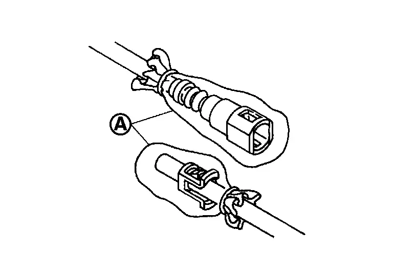
Remove lock ring for fuel level sensor unit, fuel filter and fuel pump assembly with unified fuel lock ring wrench [SST: KV101207S0 ( — )] (A) or fuel tank lock ring wrench [SST: KV10119800 ( — )] .
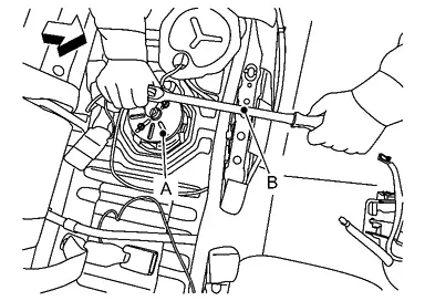
| : vehicle front | |
| B | : Spinner handle |
CAUTION:
-
To prevent lock ring wrench from being detached, securely hold down spinner handle by hand.
-
To reduce impact caused by removal operation, use long spinner handle [handle length: 60 cm (23.62 in) or more] and slowlyturn it counterclockwise.
Remove fuel level sensor unit, fuel filter and fuel pump assembly.
CAUTION:
-
Never bend float arm during removal.
-
Avoid impacts such as falling when handling components.
INSTALLATION
Note to the following, and install in the reverse order of removal.
CAUTION:
Do not reuse O-rings.
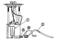
Align the connection positions and of the fuel pump and transfer tube , and insert them straight until click sound.
-
Pull on the fuel pump and transfer tube to make sure they are securely connected.
Install the transfer tube and transfer tube bracket, paying attention to the following.Install the transfer tube and transfer tube bracket in the following order.
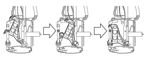
of the transfer tube bracket and the groove part fit securely.
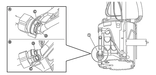
|
: Upper side |
|
: Lower side |
of transfer tube bracket with bellows part of transfer tube .
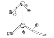
of transfer tube bracket with flat part of transfer tube .
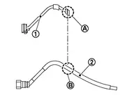
Insert transfer tube while bending the bellows part by hand to make it easier to insert the fuel pump into the fuel tank.
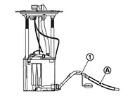
CAUTION:
Be careful not to crush or break the transfer tube.
Quick Connector
-
Connect quick connector as follows:
Check the connection for damage or any foreign materials.
Align the connector with the tube, then insert the connector straight into the tube until a click sound is heard.
After connecting, check that the connection is secure by following method.
-
Pull the tube and the connector to check they are securely connected.
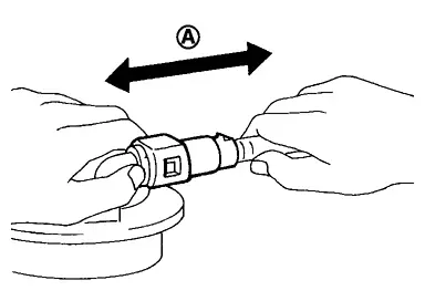
: Pull -
Visually confirm that the two retainer tabs are connected to the connector.
Inspection
INSPECTION AFTER INSTALLATION
Use the following procedure to check for fuel leakage.
Ignition switch “ON� (with engine stopped), then check connections for leakage by applying fuel pressure to fuel piping.
Start engine and let it idle and check there are no fuel leakage at the fuel system connections.
Other materials
Precautions on supplemental restraint system
This section describes the Supplemental Restraint System (SRS) in the Nissan
Armada and provides essential safety information regarding its operation. The Nissan
Armada is equipped with multiple advanced protection systems designed to work together
with seat belts to reduce the risk of injury ...
Rear Drive Shaft Boot
Exploded View
Circular clip
Dust shield
Housing
Snap ring
Ball cage/steel ball/inner race assembly
Stopper ring
Boot band
Boot
Shaft
Joint sub-assembly
: Wheel side
1: NISSAN genuine grease or an equivalent. ...
Transfer Fluid: Atx93b
Inspection
WARNING:
Jacking up or lift up the vehicle may the vehicle height to go down which cause a personal injury and/or damage to the air suspension component parts. Refer to Precaution for when Jacking and Lifting Up the vehicle with Electronic Air Suspension System.
FLUID LEAKAGECheck t ...